Will Hydra output to an AFR meter?
 08-23-2009, 05:35 AM
#1
Elite Member
Thread Starter
iTrader: (2)
Join Date: Jan 2009
Location: Columbus, OH
Posts: 4,140
Total Cats: 229
As the thread title states, I would like to know if anyone has an AFR setup that runs off of the hydra. It seems that with all of it's functions, and the fact that it has it's own WBO2 sensor, that it would be capable of outputting the correct signal to an air/fuel ratio gauge. It would be nice to not have to buy and use a new sensor and mini-computer when the Hydra already senses and computes by itself.

Reply
 0
0

0
08-24-2009, 12:49 PM
#4
Elite Member
Thread Starter
iTrader: (2)
Join Date: Jan 2009
Location: Columbus, OH
Posts: 4,140
Total Cats: 229
I suppose i figured it would require setting up a custom 2d map to output the voltage to the meter depending on the input from the WBO2.
y8s, you make it sound like it would be difficult to do. I'm getting ready to come off deployment right now, so I can't exactly play with the ECU ATM, but I know you're pretty experienced with the Hydra. On a scale of 1-10 how difficult do you think it would be to set up given a math skill of 9/10 and an electronics skill of 5/10? (Assuming, of course, that I can find an AFM with the correct voltage range to begin with.)
I am assuming that I would need to monitor the voltage of the unit at given A/F displays and then mimic the voltage output from the Hydra to the meter IOT get a proper base map, then calibrate that map based on the difference between the on-screen software AFM and the actual AFM to get a consistant reading.
Reply
0
0
08-24-2009, 01:25 PM
#5
2 Props,3 Dildos,& 1 Cat


iTrader: (8)
Join Date: Jun 2005
Location: Fake Virginia
Posts: 19,338
Total Cats: 573
most meters read like this:
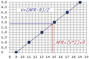
so really all you need is to figure out what voltage you're getting for what AFR in your map.
otherwise your method sounds reasonable. the only issue is that PWM isn't exactly voltage. you'll need a lowpass filter and a high PWM frequency. Maybe try a 4.7k ohm resistor in series and a 1.0uF capacitor (non polar) in parallel (one side connected at the meter (after the resistor) and one side connected to ground.
Reply
0
0
08-24-2009, 04:35 PM
#6
Elite Member
Thread Starter
iTrader: (2)
Join Date: Jan 2009
Location: Columbus, OH
Posts: 4,140
Total Cats: 229
wow, detailed info FTW!
Ill have to write all that down, like i said, 5/10 electronics (maybe 3/10?) -
resistor to get current into spec and capacitor to keep the meter from jumping all around at an unreadable pace?
Ill have to write all that down, like i said, 5/10 electronics (maybe 3/10?) -
resistor to get current into spec and capacitor to keep the meter from jumping all around at an unreadable pace?
Reply
0
0
08-24-2009, 05:07 PM
#7
2 Props,3 Dildos,& 1 Cat
iTrader: (8)
Join Date: Jun 2005
Location: Fake Virginia
Posts: 19,338
Total Cats: 573
3/10 
the resistor and capacitor form a lowpass filter.
Low-pass filter - Wikipedia, the free encyclopedia
see PWM outputs are pulses at a fixed frequency that vary in length. if you average the pulse widths over a given amount of time, you get an equivalent analog value. what the RC circuit does is essentially treat the carrier frequency signal as high frequency noise and looks at only the low speed swings in output voltage.
example:
outputting 5V at 100% duty cycle will average to ~5V
outputting 5V at 0% duty cycle will average to ~0V
outputting 5V at 50% duty cycle will average ~2.5V because you are spending half your time at 5V and half your time at zero V.
The RC circuit basically stores and releases the voltage smoothly over time.
Reply
0
0
08-25-2009, 08:12 AM
#8
Elite Member
Thread Starter
iTrader: (2)
Join Date: Jan 2009
Location: Columbus, OH
Posts: 4,140
Total Cats: 229
Thanks for sending me to the wiki, I think it's finally *clicked* now!
Also didn't realize how the PWM signals work - very good to know (and the reason for the filter in the first place ). Seems that a higher frequency PWM would indeed help the filter to work better, as suggested.
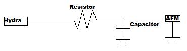
Sounds like the wiring will need to look like the attached pic.
The Hydra can do 5v and 12v PWM signals, correct?
I will definitely give this a shot when I get home, if everything works out, I'll submit a writeup.
Also didn't realize how the PWM signals work - very good to know (and the reason for the filter in the first place
). Seems that a higher frequency PWM would indeed help the filter to work better, as suggested.Sounds like the wiring will need to look like the attached pic.
The Hydra can do 5v and 12v PWM signals, correct?
I will definitely give this a shot when I get home, if everything works out, I'll submit a writeup.
Reply
0
0
 08-25-2009, 10:15 AM
#10
2 Props,3 Dildos,& 1 Cat
iTrader: (8)
Join Date: Jun 2005
Location: Fake Virginia
Posts: 19,338
Total Cats: 573
the img is correct.
the hydra doesn't do any voltage, it just switches to ground. you provide the volts. if you need 5V, use a 5V regulator off the 12V battery power. Actually, the hydra may have a 5V output but I'm not sure.
the hydra doesn't do any voltage, it just switches to ground. you provide the volts. if you need 5V, use a 5V regulator off the 12V battery power. Actually, the hydra may have a 5V output but I'm not sure.
Reply
0
0
05-22-2011, 02:01 PM
#11

Ok bringing this up as a theoretical question. Why not just splice into the wideband o2 get a signal picked up and wire it to a gauge. Run the car and watch the computer and gauge readings and make any adjustments of the difference with a bag o resistors or similar. Who cares if the Hydra sends the signal or you piggy back it as long as its the same sensor your getting the same signal. Ish. FYI I'm a newb to this and havent even gotten into my hydra ecu yet. Just bought a 99 with one this week, waiting on base maps.
Reply
0
0
08-05-2011, 04:21 PM
#12
^Sounds good... but then you have the issue of the display "fighting" over control of the sensor with the Hydra.
I asked a similar question earlier this week on another board.
[edit]
Holy old thread, Batman! My apologies. :(
I asked a similar question earlier this week on another board.
Originally Posted by MadScientistMatt
You'd have an easier time getting the Hydra to run a PWM output to drive a gauge - and I'm saying this without knowing whether the current Hydra firmware even has this feature. Putting two normal controllers on a wideband sensor is more likely to have the two fight over control of the pump cell, send in current when the other one isn't aware of the current source, and generally cause total chaos. It's possible you could design a controller to read the behavior of a wideband under a different controller, but it would probably need to be a purpose-built thing that measures current with inductive pick-ups.
[edit]
Holy old thread, Batman! My apologies. :(
Reply
0
0
11-22-2011, 07:08 PM
#13
Former Vendor

Join Date: Feb 2008
Posts: 128
Total Cats: 2
FWIW Hydra is providing their 2.7 CAN bus protocol to gauge vendors that want to write an interface, but it's a ways out from working yet. I've been telling them that getting an output for an AFR gauge is high on customer's list for the system so hopefully this will give us a way to do it in the future.
Reply
0
0
11-22-2011, 07:52 PM
#14
Boost Pope
iTrader: (8)
Join Date: Sep 2005
Location: Chicago. (The less-murder part.)
Posts: 33,019
Total Cats: 6,587
Realizing this is an old thread, I'll chime in just for the archives in case somebody stumbles upon this while searching in the future.
That would work with a narrowband (nernst-cell) sensor, which outputs a DC voltage that varies pesudo-linearly with AFR. (Well, it's not even remotely linear, actually. But there's a fixed and easy-to-document relationship. More voltage = more fuel, less voltage = less fuel.) So as long as the device you are splicing in has a relatively high input impedance, you can "share" the sensor signal between two devices with no problem. This is how el-cheepo narrowband gauges work.
Now, with a wideband sensor, things get a bit more complex. The sensor itself does not just sit there generating a DC voltage in response to AFR. Rather, the sensor and the controller work together in a closed feedback loop, wherein the sensor (which consists of multiple internal elements) strives to achieve equilibrium between a reference cell (which is exposed to atmospheric air) and a pump cell, while the ECU supplies power to, and monitors the current consumption of, the pump cell.
Unfortunately, there are relatively few non-intrusive ways of monitoring DC current in a wire externally. (You can't just splice into the wire to measure it like you can with voltage.) Granted, inductive probes exist which are capable of externally measuring DC current flow through a wire, however such devices are neither commonplace nor cheap; typically, such probes are found only in a laboratory environment. We have a Tektronix TCP202 at work, and that one costs $2,130 new. That's just for the probe itself.
Reply
0
0

Thread
Thread Starter
Forum
Replies
Last Post
Zaphod
MEGAsquirt
47
10-26-2018 11:00 PM
Motorsport-Electronics
ECUs and Tuning
0
09-05-2015 08:02 AM


