@Ben/Matt (and all) - continuous knock-retard with DIYPNP
 04-02-2010, 07:29 AM
#1
Elite Member
Thread Starter

Join Date: Mar 2006
Location: Schwarzenberg, Germany
Posts: 1,553
Total Cats: 101
Hi - I suppose Ben and Matt are the specialists with this...
I just got my car up and running after the winter again. I still have a problem with the DIYPNP.
I connected my KnocksenseMS to the DIYPNP via the ADC2/JS5. All my settings are the same from my former MS2 install.
The Knocksense gives a steady 5V (something like 4.9x volt actually) which means no knock. The DIYPNP although sees knock all the time and retards to the maximum 10degree retard... (So I switched to disabled for now.)
As I said - the knocksense is giving my the right voltages - where in the DIYPNP could I measure voltages to check what is going wrong?
Thanks
Sven

Reply
 0
0

0
04-02-2010, 10:33 AM
#3
Elite Member
Thread Starter
Join Date: Mar 2006
Location: Schwarzenberg, Germany
Posts: 1,553
Total Cats: 101
Hi Ben,
I am using the knocksense MS which is not connected to the internal knock circuit at all - just wired directly to the ADC2. Does this internal R6 (No it's R26) anyway have an influence on the sensitivity?
Thanks, Greets
Sven
I am using the knocksense MS which is not connected to the internal knock circuit at all - just wired directly to the ADC2. Does this internal R6 (No it's R26) anyway have an influence on the sensitivity?
Thanks, Greets
Sven
Reply
0
0
04-02-2010, 12:45 PM
#6
Elite Member
Thread Starter
Join Date: Mar 2006
Location: Schwarzenberg, Germany
Posts: 1,553
Total Cats: 101
Strangely enough this afternoon I opened the DIYPNP again to check the connections the 537th time - as I did know before everything was connected as supposed - I enabled the knock option again in TS and the knock retard was gone... WTF?
I tested the voltages before and got 4.97 V at the knocksense and at ADC2.
I will definitely keep an eye on this...
Edit.
@Matt - no knock enable jumper set
Thanks, Greets
Sven
I tested the voltages before and got 4.97 V at the knocksense and at ADC2.
I will definitely keep an eye on this...
Edit.
@Matt - no knock enable jumper set
Thanks, Greets
Sven
Reply
0
0
04-02-2010, 10:56 PM
#7
Supporting Vendor


iTrader: (33)
Join Date: Jul 2006
Location: atlanta-ish
Posts: 12,659
Total Cats: 134
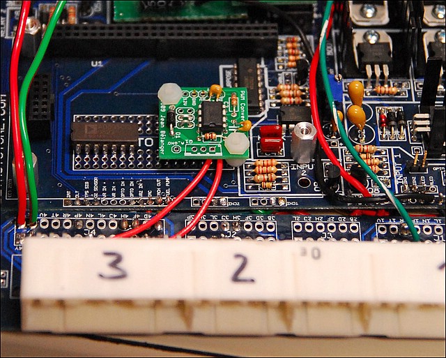
Hmm... well next time when/if the ECU thinks there's knock, hit the pins with a multimeter.
Clever use of the proto area.
Almost makes me sad that the new boards don't have the second proto area under the module (we put a LM1815 based VR conditioner and some other goodies there instead).
Clever use of the proto area.
Almost makes me sad that the new boards don't have the second proto area under the module (we put a LM1815 based VR conditioner and some other goodies there instead).
Reply
0
0
04-06-2010, 02:20 PM
#8
Elite Member
Thread Starter
Join Date: Mar 2006
Location: Schwarzenberg, Germany
Posts: 1,553
Total Cats: 101
Hi,
had the problem again today - hit the output line from the KnocksenseMS to with a DVM and got steady ~5.00 V - that line is directly connected to the ADC2.
Now I had a look at the TS menu again:
The choice there is between
MS2 AD6/JS5
MS2 AD7/JS4
I have this set to MS2 AD6/JS5 - which should be the ADC2 afaik.
ADC1 is the input of my EGT gauge.
Any ideas or suggestions?
Thanks!
Reply
0
0
04-08-2010, 03:27 PM
#12
Elite Member
Thread Starter
Join Date: Mar 2006
Location: Schwarzenberg, Germany
Posts: 1,553
Total Cats: 101
O.K. I found out what is going on - but that confuses me even more:
I have my EGT circuit attached to ADC1 and the KnocksenseMS output to ADC2,
The gauge that reads my EGT is EGTgauge6.
So I had a go and put two new gauges on my TS dash ADC6 and ADC7.
ADC6 (which would be JS5) shows values equal to my EGT, ADC 7 shows 12xx or very low like 13x - which I assume would compare with the Knocksense output. (And changes when I turn the pot on my knocksense to such a low level that the LED lights)
According to the DIYPNP manuals ADC1 is JS4 and ADC2 is JS5 - but in the pulldown menu of the knock settings I have the choice of JS5/ADC6 or JS4/ ADC7.
As I have my Knocksense attached to ADC2 I choose JS5, which gives me wrong knock readings (as I can see via my knocksense led) - when I chose JS4 I get no knock reading even when the led lights...
Something seems to be wrong - my fault?
Thanks for any suggestions...!
Edit: @Ben - Pin 16 reads 5 volts even when indicating knock.
Reply
0
0
04-09-2010, 03:18 AM
#14
Elite Member
Thread Starter
Join Date: Mar 2006
Location: Schwarzenberg, Germany
Posts: 1,553
Total Cats: 101
So this is a bug in the DIYPNP documentation I guess?
http://diyautotune.com/diypnp/docs1_...a_outputs.html
ADC1 (JS4) Baro correction, knock input, launch control, second O2 sensor, nitrous input
ADC2 (JS5) Baro correction, knock input, launch control, second O2 sensor, nitrous input
Could Ben or Matt please confirm?
http://diyautotune.com/diypnp/docs1_...a_outputs.html
ADC1 (JS4) Baro correction, knock input, launch control, second O2 sensor, nitrous input
ADC2 (JS5) Baro correction, knock input, launch control, second O2 sensor, nitrous input
Could Ben or Matt please confirm?
Reply
0
0
04-09-2010, 04:02 AM
#15
Elite Member
iTrader: (10)
Join Date: Jun 2006
Location: Athens, Greece
Posts: 5,977
Total Cats: 356
I guess so, check the schematics:
http://www.megamanual.com/ms2/pcb.htm
JS4=AD7
JS5=AD6
http://www.microsquirtmodule.com/mod_hardware.htm
AD6=SPAREADC
AD7=SPAREADC_2
So AD6=JS5=SPAREADC and AD7=JS4=SPAREADC_2
Jim
http://www.megamanual.com/ms2/pcb.htm
JS4=AD7
JS5=AD6
http://www.microsquirtmodule.com/mod_hardware.htm
AD6=SPAREADC
AD7=SPAREADC_2
So AD6=JS5=SPAREADC and AD7=JS4=SPAREADC_2
Jim
Reply
0
0
04-09-2010, 12:51 PM
#17
Elite Member
Thread Starter
Join Date: Mar 2006
Location: Schwarzenberg, Germany
Posts: 1,553
Total Cats: 101
Seem to be my fate that I always am the one to get to such points...
Nice to know what the problem was...
One more thing Matt - I think it also should be changed in the Mass Air Flow Sensors.
Board connection Processor port Firmware setting (B&G Code)
MAP AD0 MAF on MAP Pin
ADC1 AD7 MAF on Knock Pin (as we learned ADC1 is AD6)
ADC2 AD6 MAF on Baro Pin (also ADC2 is AD7 then)
I hope this gives me some extra % for my next order... ;-)
Greets
Reply
0
0

Thread
Thread Starter
Forum
Replies
Last Post
Mikel
MEGAsquirt
4
09-28-2015 04:46 PM


