Joe's revised Spark Out vs. MSExtra Manual - TC4427 Spark Output
 02-24-2015, 11:17 PM
#1
Junior Member
Thread Starter
iTrader: (1)

Join Date: Aug 2014
Location: Wisconsin
Posts: 78
Total Cats: 12
Hi All,
I know that Joe's "A Better Spark Out..." thread just got brought back from the dead for no apparent reason. I have been following the MSExtra Manual and it says using this MOSFET IC that seems to mimic Joe's "double inversion circuit." I read that whole thread and a few others but I have a question about an option in the MSExtra manual
TC4427AEPA Microchip Technology | TC4427AEPA-ND | DigiKey]Invalid Request
I'm building DIY MS2 V3.0 to run my stock '94. Going for stock ignitors and wasted spark for now. If I prove successful (getting it running & tuning it), I'll be moving to COP.
The MSExtra Manual (5.3.1.3) states that with this logic coil spark circuit, "Coils do not receive a spurious signal pulse at power on", which leads me to think it behaves similarly. However, looking at the details on Digi-Key, it states that the Input Type is Non-Inverting. This confused me (as if the whole "spark inverted" thing within TunerStudio wasn't confusing enough.)
I admit that I don't have as good a grasp on electrical systems as I aim to achieve in the future. As it is now, I can't make much sense of the circuit diagrams that show the internal workings of the IC to verify that this will have the same effect as Joe's Better Spark Out Circuit (grounding the circuit when inactive and inverting what the CPU outputs to the coil)
http://www.microchip.com/mymicrochip...cname=en011753
Even searching for "4427" turned up with nothing relevant here and surprisingly few relevant results even Googling (like 5). I realize which end of the scale of expertise on this subject I fall towards. Just hoping for some clarification and a learning opportunity. Thanks.

Reply
 0
0

0
02-24-2015, 11:24 PM
#2
Junior Member
Thread Starter
iTrader: (1)
Join Date: Aug 2014
Location: Wisconsin
Posts: 78
Total Cats: 12
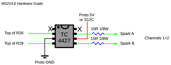
So that people don't have to go link hopping, this how the MSExtra manual shows to wire up the chip:
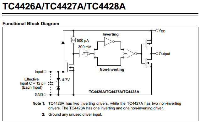
And this one that is from the IC's data sheet showing how it works on the inside:
And this one that is from the IC's data sheet showing how it works on the inside:
Reply
0
0
02-25-2015, 11:53 AM
#4
Junior Member
Thread Starter
iTrader: (1)
Join Date: Aug 2014
Location: Wisconsin
Posts: 78
Total Cats: 12
Thank you Braineack. The MS3X may be an option in the future but presently, I am interested in this chip.
I am realizing as I learn more about the MegaSquirt, how it has been adapted to fulfill many capabilities it was never originally designed to handle.
I am realizing as I learn more about the MegaSquirt, how it has been adapted to fulfill many capabilities it was never originally designed to handle.
Last edited by 4strings; 02-25-2015 at 11:56 AM. Reason: expanded thoughts
Reply
0
0
02-25-2015, 12:29 PM
#6
Boost Czar


iTrader: (62)
Join Date: May 2005
Location: Chantilly, VA
Posts: 79,493
Total Cats: 4,080
it appears it'll work as you intend. 
ive never seen these in use, it's very new to the documentation, but im assuming it's more or less similar to the IC they use in the Expander board for spark outputs.
ive never seen these in use, it's very new to the documentation, but im assuming it's more or less similar to the IC they use in the Expander board for spark outputs.
Reply
0
0
02-25-2015, 02:25 PM
#8
Junior Member
Thread Starter
iTrader: (1)
Join Date: Aug 2014
Location: Wisconsin
Posts: 78
Total Cats: 12
The question is will this chip invert the signal from ecu like Joe Perez's Better Spark Out Circuit; hopefully preventing pop on cranking and protecting the ignition coils when flashing.
Thank you Braineack. So the output option in Tuner Studio will also mimic Joe's as "spark output = inverted"?
Reply
0
0
02-25-2015, 09:42 PM
#9
Junior Member

Join Date: Feb 2015
Location: Texas
Posts: 53
Total Cats: -63
??? on Joe's "A Better Spark Out are the led on all the time or turn on when the spark happens or do i have some thing not wired right ?? i test the spark in tuner and it works but dose not of the trigger for it . and its is taking for ever to fine stuff and pic are missing can we get them back up
Reply
0
0
02-25-2015, 09:51 PM
#10
Junior Member
Thread Starter
iTrader: (1)
Join Date: Aug 2014
Location: Wisconsin
Posts: 78
Total Cats: 12
??? on Joe's "A Better Spark Out are the led on all the time or turn on when the spark happens or do i have some thing not wired right ?? i test the spark in tuner and it works but dose not of the trigger for it . and its is taking for ever to fine stuff and pic are missing can we get them back up
Did you test your spark outputs before you did the Better Spark Out? Since this circuit is triggering your ignition coils, I'm inclined to think that they should not be solid on.
Reply
0
0
02-25-2015, 10:44 PM
#11
Tweaking Enginerd
iTrader: (2)

Join Date: Mar 2013
Location: Boulder, CO
Posts: 1,773
Total Cats: 354
Based in the functional block diagram this circuit should invert. The input clamp prevents back drive. The mosfet conducts when the input is high. The current source shorts when the mosfet conducts. The schmitt trigger inverts, fillowed by another invert, and then the totem pole. This is from memory, can't see the diagram while posting, and I am too lazy to open another window. Three inverts => inverted output. Totem pole => push-pull (source-sink)
Edit: I just reviewed the data sheet as well as the digismack page and I can see why you are confused. The timing diagram looks like you need the 26 for an invert. I would suggest that you buy the dual(28) or both the 26 and 27 and bench test.
Additional corrections: the totem pull is another invert, and I misremembered the configuration of the input zener, it provides input reverse polarity protection.
F, it is late. I should just keep my mouth shut.
Last edited by Ted75zcar; 02-25-2015 at 11:03 PM.
Reply
0
0
02-25-2015, 11:09 PM
#12
Junior Member
Join Date: Feb 2015
Location: Texas
Posts: 53
Total Cats: -63
MiataFox, This is my first rodeo, therefore I wouldn't consider myself an expert. If I were you, I would create your own thread about the unique problem you are experiencing complete with a detailed description of your build and pictures as well. You may get a better response that way. As a side note, both the comments you've left about this were difficult to read in their own rights (grammer/spelling).
Did you test your spark outputs before you did the Better Spark Out? Since this circuit is triggering your ignition coils, I'm inclined to think that they should not be solid on.
Did you test your spark outputs before you did the Better Spark Out? Since this circuit is triggering your ignition coils, I'm inclined to think that they should not be solid on.
i'm going on what i have found but its just parts of post . and i know my grammar is not the best and i use spell check .. what can i say i'm more in to cars then writing books but thanks for the help
Reply
0
0
02-26-2015, 01:32 AM
#13
Junior Member
Thread Starter
iTrader: (1)
Join Date: Aug 2014
Location: Wisconsin
Posts: 78
Total Cats: 12
I have and the guys that know this stuff i guess do not like me ... for i have had no help at all and they will not fix there old post that say look at the pic below and the pic gone .
i'm going on what i have found but its just parts of post . and i know my grammar is not the best and i use spell check .. what can i say i'm more in to cars then writing books but thanks for the help
i'm going on what i have found but its just parts of post . and i know my grammar is not the best and i use spell check .. what can i say i'm more in to cars then writing books but thanks for the help
Reply
0
0
02-26-2015, 09:44 AM
#18
Supporting Vendor

Join Date: Sep 2006
Posts: 2,332
Total Cats: 67
The question is will this chip invert the signal from ecu like Joe Perez's Better Spark Out Circuit; hopefully preventing pop on cranking and protecting the ignition coils when flashing.
Thank you Braineack. So the output option in Tuner Studio will also mimic Joe's as "spark output = inverted"?
Thank you Braineack. So the output option in Tuner Studio will also mimic Joe's as "spark output = inverted"?
Reply
0
0
02-26-2015, 05:39 PM
#19
Junior Member
Join Date: Feb 2015
Location: Texas
Posts: 53
Total Cats: -63
and i set it up brain
 way and it still did not work but still put out spark if i use the test in tuner
so what e'm i missing ????
Reply
0
0


