My MS3x build questions... it's alive on the stim.
 02-05-2012, 07:40 AM
#1
Elite Member
Thread Starter

Join Date: Mar 2006
Location: Schwarzenberg, Germany
Posts: 1,553
Total Cats: 101
Hi,
now that I took the step and got on to build my MS3x after Franks MS3X(PNP) described here: http://westfieldmx5.devocht.com/megasquirt/99-05-ms3/ I sure as hell have the first problems...
First the good things - I did build all the things on the 3.0 board after Franks description and it seems to work - I could actually flash the firmware and load an MSQ. (So thats fine to me.)
I measured all the voltage and get correct 5V readings -

But at the 12V points I only get 10.75 V... (is that a problem) the power is coming from a Jimstim (reading 11.5 V there.)
How can I check if R52 is set correctly? I did the calibration of R56.
Please help me about this...
Now the bloody problem - when I took of the daughterboard to go on, I sure as hell bent the two lower pins (1 and 40) and Nr. 1 broke off when I tried to bend it back... I could solder the pin back on, and things seem to work (but I am afraid if I have to take the board off once more). I think I need to send the board to James in the U.K. to get new pins soldered... (or maybe I could go to an electronics company here and ask them to solder new pins on...?)
Other than that - at the moment I am happy that I can read and write to the MS... Now get on with the wiring to the 64pin ECU connector.
Greets
now that I took the step and got on to build my MS3x after Franks MS3X(PNP) described here: http://westfieldmx5.devocht.com/megasquirt/99-05-ms3/ I sure as hell have the first problems...
First the good things - I did build all the things on the 3.0 board after Franks description and it seems to work - I could actually flash the firmware and load an MSQ. (So thats fine to me.)
I measured all the voltage and get correct 5V readings -
But at the 12V points I only get 10.75 V... (is that a problem) the power is coming from a Jimstim (reading 11.5 V there.)
How can I check if R52 is set correctly? I did the calibration of R56.
Please help me about this...
Now the bloody problem - when I took of the daughterboard to go on, I sure as hell bent the two lower pins (1 and 40) and Nr. 1 broke off when I tried to bend it back...
I could solder the pin back on, and things seem to work (but I am afraid if I have to take the board off once more). I think I need to send the board to James in the U.K. to get new pins soldered... (or maybe I could go to an electronics company here and ask them to solder new pins on...?)Other than that - at the moment I am happy that I can read and write to the MS... Now get on with the wiring to the 64pin ECU connector.
Greets
Last edited by Zaphod; 02-06-2012 at 01:07 PM.

Reply
 0
0

0
02-05-2012, 10:59 AM
#3
Senior Member

Join Date: Nov 2007
Location: Belgium
Posts: 999
Total Cats: 73
You could remove an unused pin like IAC1B (37) or IAC2B (35) and replace pin 1 with it. See http://msextra.com/doc/general/pix/v3pcb_1-ms3.gif ps, if you have suggestions for my how-to please share them so I can make the instructions more clear.
Reply
0
0
02-05-2012, 11:00 AM
#4
Boost Czar


iTrader: (62)
Join Date: May 2005
Location: Chantilly, VA
Posts: 79,488
Total Cats: 4,077
Just resolder the pin and move along.
next time you pull off the board, use a long solid device, like a table knife, to pry it up from the underside on each side, then once you can lift it straight.
next time you pull off the board, use a long solid device, like a table knife, to pry it up from the underside on each side, then once you can lift it straight.
Reply
0
0
02-05-2012, 12:02 PM
#5
Elite Member
Thread Starter
Join Date: Mar 2006
Location: Schwarzenberg, Germany
Posts: 1,553
Total Cats: 101
You could remove an unused pin like IAC1B (37) or IAC2B (35) and replace pin 1 with it. See http://msextra.com/doc/general/pix/v3pcb_1-ms3.gif ps, if you have suggestions for my how-to please share them so I can make the instructions more clear.
What did you prepare for?
Reply
0
0
02-05-2012, 12:24 PM
#6
Senior Member
Join Date: Nov 2007
Location: Belgium
Posts: 999
Total Cats: 73
I have an S2000 instrument cluster and needed some pins to bring in the VR signal from the transmission. I convert that to a square wave (extra VR in proto) and send it to JB's PWM converter to multiply by 32. That goes back out the MS towards the speedo.
I have the oil pressure signal coming in on ADC13 to have an oil pressure gauge in TunerStudio. I'm sending the signal back out to my oil pressure light as well (no oil pressure gauge in the S2000 cluster).
I'm also planning on installing cops and a shift light which will take up a fair amount of outputs.
Reply
0
0
02-06-2012, 01:14 PM
#8
Elite Member
Thread Starter
Join Date: Mar 2006
Location: Schwarzenberg, Germany
Posts: 1,553
Total Cats: 101
So I have my build done quite far (gonna post pics soon).
One more question though - I wan't to build my EGT circuit in the proto area of the v3.0 board - where can I take the +12V from - means where on the board have we got +12v usable for the circuit.
As I do the MS3Xpnp like Frank S12c is used for the jumper to JS9, Pin 28 is used for the jumper wire to the +12v to IAC, middle pin of Q2 is jumpered to pin 1B of my ECU connector. Anywhere else to take from or take from one of these points?
Thanks!
Reply
0
0
 02-06-2012, 02:18 PM
#14
Supporting Vendor

iTrader: (33)
Join Date: Jul 2006
Location: atlanta-ish
Posts: 12,659
Total Cats: 134
You will need to build a conditioner (amplifier). You can not interface the thermocouple directly. Several options are shown in the manual:
http://www.msextra.com/doc/ms3/egt.html
We stock a small mod kit that includes the AD595 thermocouple amp.
http://www.diyautotune.com/catalog/g...put-p-458.html
Maybe you find one locally, if not they're on our site.
http://www.msextra.com/doc/ms3/egt.html
We stock a small mod kit that includes the AD595 thermocouple amp.
http://www.diyautotune.com/catalog/g...put-p-458.html
Maybe you find one locally, if not they're on our site.
Reply
0
0
02-06-2012, 03:33 PM
#16
Senior Member
Join Date: Nov 2007
Location: Belgium
Posts: 999
Total Cats: 73
You can take 12V at the non-banded side of D3 (anode). If you put a jumper in D3, you even have 4 new 12V points (C13, C14, D21 and pin 6 of U4).
Last edited by WestfieldMX5; 01-11-2017 at 02:45 PM.
Reply
0
0
02-07-2012, 02:45 AM
#17
Elite Member
Thread Starter
Join Date: Mar 2006
Location: Schwarzenberg, Germany
Posts: 1,553
Total Cats: 101
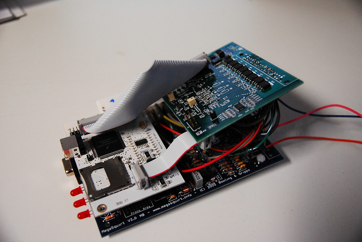
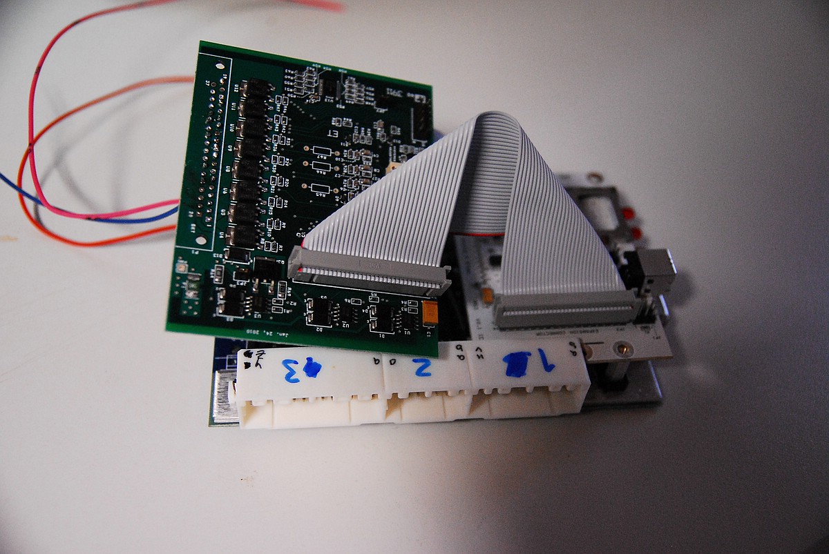
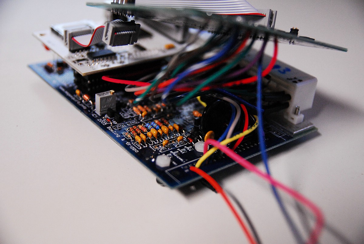
Here are the promised pics:
I got some more questions:
As I wired my Zeitronix WB in the DIYPNP directly through the DB15 connector (+12V and ground / sensor ground) and want to do this here as well - which grounds should I take - pins 14-16 on the main connector or rather the ground pads at the proto area? I ask because I am afraid of noise - at the DIYPNP there are extra grounds for noisy things...
Reply
0
0


