MS build thread - for a 99 but 1,6 (Euro) MX-5
 09-21-2008, 03:40 AM
#1
Elite Member
Thread Starter

Join Date: Mar 2006
Location: Schwarzenberg, Germany
Posts: 1,553
Total Cats: 101
Abe (as well as Joe, Jason, Braineack and many other) was a big help with a lot of questions I got with my MS install in my very uncommon 99 1,6 (only available in Europe) and he asked me to do a build thread - to save all the knowledge and discussion in a thread...
As there is at least one more 99 1,6 in here which is trying the MS install - I will try to give as much information as possible.
First some facts to my car:
1999 (actually 1998 build) 1,6 NB
Garrett T25 turbo (Abe has the same on his bike... )
)
VW Sharan Van air/air intercooler
oil-cooler
self-made air intake box behind driver side headlight
460cc RX7 injectors
DIY dual-feed fuel rail
recirculating Audi S3 BOV
complete 2,5" stainless exhaust including downpipe and 200cell metall catalytic converter
The history of my management systems:
- original ECU with changes made by HGP (chip added) - the only TUV approved turbo system for the Miata/MX-5 here in Germany - was running really lean with the good flowing exhaust etc.
- Emanage blue with olderguys autotune - much better than the first - but a lot of hickups in the transition to boost etc.
- Emanage ultimate - better than the two above - but not really getting a clean tune and fighting with my additional EBC
so my next step was to go the MS route...
I ordered the following at DIYautotune.com:
*******
MS1357-C MegaSquirt-1 PCB v3.57 (SMT) Engine
Management System
MOD_13571... Modifications for Miata / DSM ignition
input and output on a V3.57 board. The
CKP signal comes in on pin 24 and the
CMP signal comes in on pin 25. Spark
output A comes out on pin 36, and spark
output B comes out on pin 31.
MOD_1357-... Add jumper for KnockSenseMS to
Megasquirt-I V3.57. Run a jumper from
JS10 to DB15 pin 3.
MOD_1357-... Launch control input mod on pin 29
MOD_1357-... Add boost control mod-kit to V3.57 board
and bring output out on pin 27 on the
DB37.
JimStim-C JimStim v1.4 Assembled Unit
'JimStim' Stimulator with Wheel Simulator
version 1.4
SM-WireBund 23" Wire Bundle -- Same wire used in
harnesses, color coded and printed
labeling. Great for building a harness or
wiring up connector to the factory
connector.
*******
I also orderd a wiring extension for the 99 at boomslang.com as I will be attempting a parallel install - due to the Emissions testing we have over here.
After a mere 3 weeks - running through the German customs etc. I received the package.
Now I did the wiring first:
I wired everything to the DB 37 connector and did the grounds ABE-style with a complete bracket for all grounds at the DB37 made of housing wiring.
https://www.miataturbo.net/forum/att...1&d=1221987921
I got myself a 90-97 CAS over here at ebay.
The attempt to install the CAS at my car failed - because the intake cam (where all the 1,6 cars have the CAS mounted) has no "fork" at the end to hold the CAS's rotator... Damn!
https://www.miataturbo.net/forum/att...1&d=1221987921
Now I have a discussion running in this thread about how to go on:
https://www.miataturbo.net/forum/showthread.php?t=25351
and here:
https://www.miataturbo.net/forum/showthread.php?t=25662
A little sidenote - the 99 1,6 electronics are mostly the same as the 99 1,8 ones, all the sensors etc.
There seem to be two ways now:
1. Go the MS2 route - order a MS2 daughterboard and Abe's CKP/CMP circuit
2. Go the MS1 route futher - with Jasons circuit or a circuit that will develop from Joe's and Jason's discussion
I am a little undecided at this point...
I am sure I forgot a lot of things - I will edit and add as I remember and as I get the pics off my mobile phone.
As there is at least one more 99 1,6 in here which is trying the MS install - I will try to give as much information as possible.
First some facts to my car:
1999 (actually 1998 build) 1,6 NB
Garrett T25 turbo (Abe has the same on his bike...
)VW Sharan Van air/air intercooler
oil-cooler
self-made air intake box behind driver side headlight
460cc RX7 injectors
DIY dual-feed fuel rail
recirculating Audi S3 BOV
complete 2,5" stainless exhaust including downpipe and 200cell metall catalytic converter
The history of my management systems:
- original ECU with changes made by HGP (chip added) - the only TUV approved turbo system for the Miata/MX-5 here in Germany - was running really lean with the good flowing exhaust etc.
- Emanage blue with olderguys autotune - much better than the first - but a lot of hickups in the transition to boost etc.
- Emanage ultimate - better than the two above - but not really getting a clean tune and fighting with my additional EBC
so my next step was to go the MS route...
I ordered the following at DIYautotune.com:
*******
MS1357-C MegaSquirt-1 PCB v3.57 (SMT) Engine
Management System
MOD_13571... Modifications for Miata / DSM ignition
input and output on a V3.57 board. The
CKP signal comes in on pin 24 and the
CMP signal comes in on pin 25. Spark
output A comes out on pin 36, and spark
output B comes out on pin 31.
MOD_1357-... Add jumper for KnockSenseMS to
Megasquirt-I V3.57. Run a jumper from
JS10 to DB15 pin 3.
MOD_1357-... Launch control input mod on pin 29
MOD_1357-... Add boost control mod-kit to V3.57 board
and bring output out on pin 27 on the
DB37.
JimStim-C JimStim v1.4 Assembled Unit
'JimStim' Stimulator with Wheel Simulator
version 1.4
SM-WireBund 23" Wire Bundle -- Same wire used in
harnesses, color coded and printed
labeling. Great for building a harness or
wiring up connector to the factory
connector.
*******
I also orderd a wiring extension for the 99 at boomslang.com as I will be attempting a parallel install - due to the Emissions testing we have over here.
After a mere 3 weeks - running through the German customs etc. I received the package.
Now I did the wiring first:
I wired everything to the DB 37 connector and did the grounds ABE-style with a complete bracket for all grounds at the DB37 made of housing wiring.
https://www.miataturbo.net/forum/att...1&d=1221987921
I got myself a 90-97 CAS over here at ebay.
The attempt to install the CAS at my car failed - because the intake cam (where all the 1,6 cars have the CAS mounted) has no "fork" at the end to hold the CAS's rotator... Damn!
https://www.miataturbo.net/forum/att...1&d=1221987921
Now I have a discussion running in this thread about how to go on:
https://www.miataturbo.net/forum/showthread.php?t=25351
and here:
https://www.miataturbo.net/forum/showthread.php?t=25662
A little sidenote - the 99 1,6 electronics are mostly the same as the 99 1,8 ones, all the sensors etc.
There seem to be two ways now:
1. Go the MS2 route - order a MS2 daughterboard and Abe's CKP/CMP circuit
2. Go the MS1 route futher - with Jasons circuit or a circuit that will develop from Joe's and Jason's discussion
I am a little undecided at this point...
I am sure I forgot a lot of things - I will edit and add as I remember and as I get the pics off my mobile phone.
Last edited by Zaphod; 10-07-2008 at 02:21 AM.

Reply
 0
0

0
09-23-2008, 10:44 AM
#2
Elite Member
Thread Starter
Join Date: Mar 2006
Location: Schwarzenberg, Germany
Posts: 1,553
Total Cats: 101
Hi,
no real news up to now -
I asked Matt at DIY to help Jason and Joe out with the MS1 - OEM sensors circuit - it looks like this thing is underway.
Also I asked Matt to tell me what I need to convert to a MS2 - or if it is possible with my 3.57 board at all... and what I have to change at the mods that have been done to the board at DIY.
So no MS1 / MS2 decision now...
I'll keep you updated.
The same second came an answer from Matt:
*Ok, that was a bit of an ambiguous question that Jason had, but I've
done my best to answer it.
You can put a MS2 daughterboard on it to convert it to an MS2, although
there's some controversy about exactly what mods it needs to work with
the NB sensors.
Thanks,
Matt Cramer
DIYAutotune.com Technical Support*
Reply
0
0
09-23-2008, 08:36 PM
#3
Boost Pope


iTrader: (8)
Join Date: Sep 2005
Location: Chicago. (The less-murder part.)
Posts: 33,015
Total Cats: 6,587
I've been keeping to myself on this to a degree, however I really suspect that switching to an MS2 is going to be the easiest way to get your car up and running. You will need to make some modifications to the main board. The MS2 requires +12 on JS9, the second trigger input is on a different pin, etc.
On paper, the same input mod as the MS1/NA should work, however experience has proven it to be problematic. That would suggest building Abe's opamp-based circuit, which is simple but has a high parts count.
JasonC SBB has drawn a circuit with a much lower parts count, based on a little schmitt-triggered inverting logic gate. I honestly don't know if it's been tested. Both circuits are here: https://www.miataturbo.net/forum/showthread.php?t=25789
Reply
0
0
09-24-2008, 02:35 AM
#4
Elite Member
Thread Starter
Join Date: Mar 2006
Location: Schwarzenberg, Germany
Posts: 1,553
Total Cats: 101
Thanks Joe,
as Jason has designed me a circuit for the MS1 I will try this way - as it is the fastest way to hopefully get my car running.
See here:
https://www.miataturbo.net/forum/sho...t=25351&page=3
I will keep you up to date how things are going - the circuit first has to make its way over the ocean...
If all the things don't work out - I will be going the MS2 route (maybe as standalone) over winter.
Greetings
Reply
0
0
10-03-2008, 10:14 AM
#5
Elite Member
Thread Starter
Join Date: Mar 2006
Location: Schwarzenberg, Germany
Posts: 1,553
Total Cats: 101
Hi,
Jason engineered me a circuit to convert the NB CKP/CMP signals to a NA-like signals...
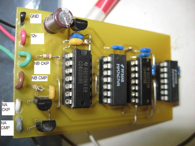
The circuit converts the signal like that:
original

converted

I received the unit yesterday and wired it in today. I get a RPM reading and a pulsewidth (when trying to start).
I tried to start the car but it doesn't start - at one point I got a slight popping like a small misfire. (What would mean, that I do get spark and fuel)
Could someone please take a look at the little log I did and the msq if especially the rpm reading looks sensible.
https://www.miataturbo.net/forum/att...1&d=1223043752
https://www.miataturbo.net/forum/att...1&d=1223043752
Jason engineered me a circuit to convert the NB CKP/CMP signals to a NA-like signals...
The circuit converts the signal like that:
original
converted
I received the unit yesterday and wired it in today. I get a RPM reading and a pulsewidth (when trying to start).
I tried to start the car but it doesn't start - at one point I got a slight popping like a small misfire. (What would mean, that I do get spark and fuel)
Could someone please take a look at the little log I did and the msq if especially the rpm reading looks sensible.
https://www.miataturbo.net/forum/att...1&d=1223043752
https://www.miataturbo.net/forum/att...1&d=1223043752
Reply
0
0
10-03-2008, 11:58 AM
#6
Boost Pope
iTrader: (8)
Join Date: Sep 2005
Location: Chicago. (The less-murder part.)
Posts: 33,015
Total Cats: 6,587
Hmmmmmmmmmmmmmm.
(scratches head)
The setup of your MSQ looks OK insofar as the basics are concerned- theb wheel decoder appears to be properly set up.
The data in your log bothers me however.
For one, I don't seen any changes at all in MAP. I would not expect to see it stuck at exactly 93 kPa at all times, whether you are cranking or not. But that's not the most disturbing thing.
By looking at the portc values, and decoding them into binary, we can see the nitty-gritty details of what's going on with your CMP input and your two spark outputs. The log is not a 100% accurate indicator on these ports (due to the sampling times involved) but it usually gives you some useful clues.
I am not seeing any activity at all on the SparkA output (portc-0), what activity I do see on SparkB (portc-1) doesn't look right, and on portc-4, where your CMP signal should be seeing nice, regular pulses, I'm just seeing what looks like a tiny amount of random noise.
I'll give you an example of what I'm talking about. Below is a tiny section of what normal PortC data should look like. This is taken from my engine at idlee, back when I was still using a CAS. Notice that bits 0 and 1 (on the right) toggle from 1 to 0 (briefly) at regular internals. Every 0 in those columns is a spark. Also, but 4 toggles from 0 to 1 at fairly regular internals. Every 1 is a CMP input pulse. (Again, I remind you that not every pulse is guaranteed to be caputed here, but it does show a consistant trend.)
00010101
00000111
00000111
00000111
00000111
00000110
00010111
00000111
00000111
00010101
00000111
00000111
00000111
00000111
00000111
00010111
00010111
00000110
00000111
00010111
00000111
00010101
Now, here's a section of data from your log:
00000011
00000011
00000011
00000011
00000011
00000011
00000011
00000011
00000011
00000011
00000011
00000001
00000001
00000001
00000001
00000001
00000001
00000001
00000001
00000001
00010001
00000001
00000001
00000001
00000001
00000001
00000001
00000001
00000001
00000001
00000001
00000001
00000001
00000001
00000001
00010001
00000001
00000001
00000001
00000001
00000001
00000001
00000001
00000001
00000001
00000001
00000001
00000001
00000001
00000001
00000001
00000001
00000001
00000001
00000001
00000001
00000001
00000001
00000001
00000001
00000001
00000001
There are a couple of bit 4 events, but not in any orderly sequence. Nothing on SparkA, and a seemingly confused SparkB.
I suspect that we have a problem with the CMP input, possibly concerning its relationship to the CKP output.
Jason, do we have any scope captures of the circuit you sent Zaphod in action?
Reply
0
0
10-03-2008, 12:08 PM
#7
Elite Member
Thread Starter
Join Date: Mar 2006
Location: Schwarzenberg, Germany
Posts: 1,553
Total Cats: 101
Well MAP - I dont have a line connected at the moment. But I thought this shouldn't be a problem.
If the spark is wrong - but why don't I get a spark with the OEM ignition system...? (can smell fuel - but get no spark if I pull a plug and hold it to ground)
Does anyone have a pic of the 3.57 board with the CKP/CMP mods. I had a look at mine yesterday and was not sure what the CKP mod is - Matt told me there should be something done to JP1 - but there is nothing on my board... at least nothing I can obviously see) Matt have you got a pic?
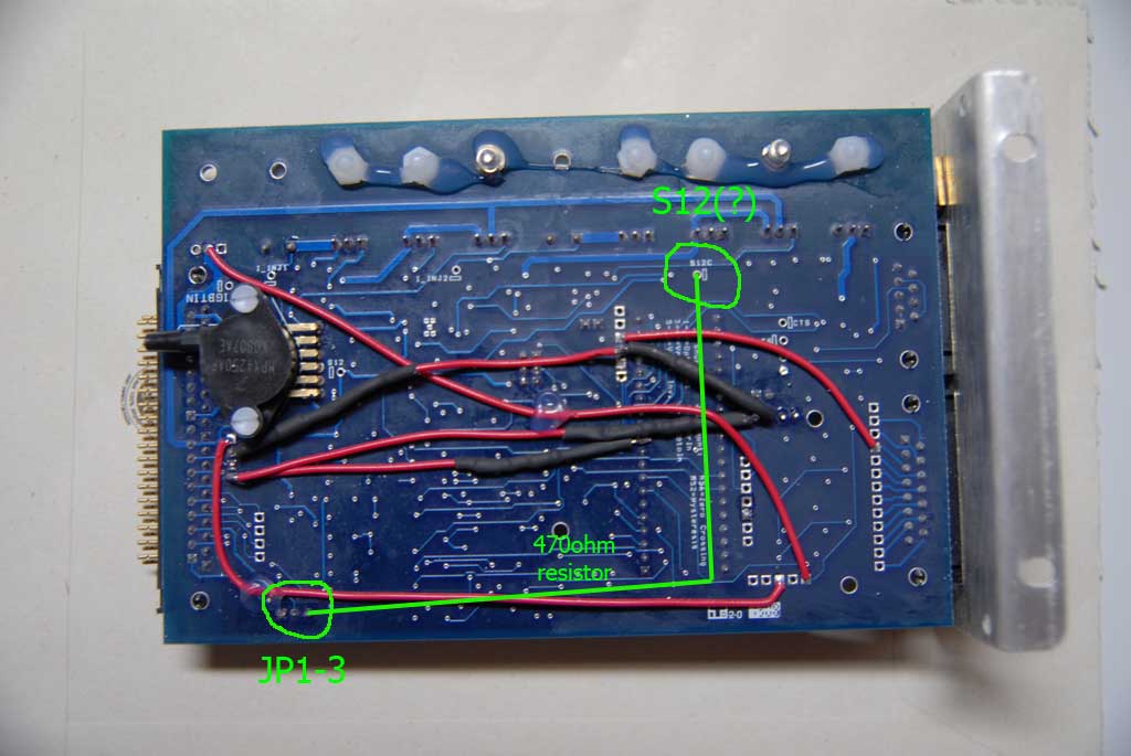
Edit: After a little chat with Matt - looks like the CKP mod is missing at my 3.57 board... Now I have to source a 470 ohm resistor to wire between S12 and pin3 of JP1.
Could this cause anything of the above?
Greets
If the spark is wrong - but why don't I get a spark with the OEM ignition system...? (can smell fuel - but get no spark if I pull a plug and hold it to ground)
Does anyone have a pic of the 3.57 board with the CKP/CMP mods. I had a look at mine yesterday and was not sure what the CKP mod is - Matt told me there should be something done to JP1 - but there is nothing on my board... at least nothing I can obviously see) Matt have you got a pic?
Edit: After a little chat with Matt - looks like the CKP mod is missing at my 3.57 board... Now I have to source a 470 ohm resistor to wire between S12 and pin3 of JP1.
Could this cause anything of the above?
Greets
Last edited by Zaphod; 10-03-2008 at 12:47 PM.
Reply
0
0
10-03-2008, 12:59 PM
#8
Boost Pope
iTrader: (8)
Join Date: Sep 2005
Location: Chicago. (The less-murder part.)
Posts: 33,015
Total Cats: 6,587
I can give you some direction on CMP. I'd expect to see a 470 ohm resistor between a source of +5 and either JS8 or pin 11 of the CPU socket. Then, a 1k resistor from JS8 or CPU pin 11 to the IAC1A pad near the DB37, and finally a 0.1uf capacitor between this point and ground.
Reply
0
0
10-03-2008, 01:08 PM
#9
Elite Member
Thread Starter
Join Date: Mar 2006
Location: Schwarzenberg, Germany
Posts: 1,553
Total Cats: 101
No problem with the CMP mod - that one ist perfectly done (I removed the 1uF resistor due to Jasons advice in the other thread).
I dont have access to the 470ohm resistor anyway - so no problem to wait
Greets
I dont have access to the 470ohm resistor anyway - so no problem to wait
Greets
Reply
0
0
10-03-2008, 01:34 PM
#10
Boost Pope
iTrader: (8)
Join Date: Sep 2005
Location: Chicago. (The less-murder part.)
Posts: 33,015
Total Cats: 6,587
Ok, I've gotten confirmation from DIY that resistor R57 is in fact not installed on the 3.57 boards by default. So you should be OK to install the 470 ohm resistor from +12 to JP1-3.
Reply
0
0
10-03-2008, 01:53 PM
#12
Good luck with it all...
Reply
0
0
10-03-2008, 05:45 PM
#13
Boost Pope
iTrader: (8)
Join Date: Sep 2005
Location: Chicago. (The less-murder part.)
Posts: 33,015
Total Cats: 6,587
For that matter, I really don't understand what it's supposed to do in the first place. Abe, Jason (etc), would you guys mind taking a look at the 3.57 schematic and giving me your opinion? It's on page 3 at A4. http://www.megamanual.com/357/hardware.htm
Are they proposing to drive the U3 LED with that thing? 5v through two diodes and 1,390 ohms, assuming a VF of 1.2 on U3, gives you a whopping 1.7ma! I just don't see the LED operating at that level.
Insofar as the operation of the thing is concerned, the MS1 is edge-triggered on the wheel inputs just like the MS2 is. While the primary trigger is a hardware IRQ, this one is a GPIO pin that gets polled. Still and all, the code is only looking at edges on it- so long as it falls at the correct moment, the software doesn't give a **** when it rises. (actually, on the 2'nd trigger you can set it to be rising or falling detect.)
The binary dumps I posted are a decode of one of the four port registers in the CPU. It's one of the neat tricks you can pull rather easily when you code in God's Language, rather than that new-age C stuff...
 All you do is LDA PORTx (to put the data into the accumulator) and then just squirt the accumulator out the serial port. It's part of the regular datastream that MT writes into the log.
Basically, they're just giving you a running tally of the status of I/O pins 7 thru 11 on the CPU, regardless of what the software is doing with them. Think of it as a software-based JTAG boundary scanner. Since there is only one register for each port (regardless of the direction of each individual pin) this one register gives you both the status of the inputs as well as the command status of the outputs. So by looking at PTC, bits 0 and 1 are what the software is writing to command the SparkA and SparkB outputs, and bit 4 is what the CPU is reading when it polls to determine CMP status.
Reply
0
0
10-03-2008, 06:59 PM
#14
Huh... That is damned odd. I wonder why Justin insisted that the resistor was not installed on their boards. It does definitely need to come off.
For that matter, I really don't understand what it's supposed to do in the first place. Abe, Jason (etc), would you guys mind taking a look at the 3.57 schematic and giving me your opinion? It's on page 3 at A4. http://www.megamanual.com/357/hardware.htm
Are they proposing to drive the U3 LED with that thing? 5v through two diodes and 1,390 ohms, assuming a VF of 1.2 on U3, gives you a whopping 1.7ma! I just don't see the LED operating at that level.
I think all those diodes and resistors are in there as tuning points, to put in more or take one some as needed for different situations (isn't this supposed to be used for high voltage isolation anyway?) Anyway, I agree is you, it looks pretty silly that way, droping less than 5V though more than 1k. I guess you could look up the spec on the opto to find out what it needs to see, but all directions I've seen were to skip this or that diode, resistor, depending on your use.
Insofar as the operation of the thing is concerned, the MS1 is edge-triggered on the wheel inputs just like the MS2 is. While the primary trigger is a hardware IRQ, this one is a GPIO pin that gets polled. Still and all, the code is only looking at edges on it- so long as it falls at the correct moment, the software doesn't give a **** when it rises. (actually, on the 2'nd trigger you can set it to be rising or falling detect.)
Ah, if it's only the cam then it makes sense not to be interupt driven (though you VVT users will rue the day you chose to run MS-I.)... It is nice you can get it out, though I imagine it's not hard to do the same in C. You might just have to put it in english.
Reply
0
0
10-03-2008, 08:15 PM
#15
Boost Pope
iTrader: (8)
Join Date: Sep 2005
Location: Chicago. (The less-murder part.)
Posts: 33,015
Total Cats: 6,587
but all directions I've seen were to skip this or that diode, resistor, depending on your use.
Hello? McFly? Anybody home? I just can't think of any set of circumstances under which this resistor can possibly do anything useful.
I wonder- has anybody ever determined with any degree of certainty what the maximum sink current on the NA CAS outputs is?
Accumulator. Like all those condensors in my electriks storing up the magnetic willpower of.... ok, I dunno. But it sounds silly.

You pretty boys with your high level languages and your fancy #includes...
When it comes down to critical embedded systems, I just don't trust a compiler to produce optimal code any more than I'd trust Babelfish to elegantly translate the complete works of Фёдор Достое́вский.
Ah, if it's only the cam then it makes sense not to be interupt driven (though you VVT users will rue the day you chose to run MS-I.)...
This is the first time I'v really looked at the MS2 in this regard, but I note that they're leaving pin 24 (IRQ) unconnected, and feeding the primary and secondary triggers into GPIO pins that appears to interface w/ the TIM (PT0 and PT5). I assume that the timer is being used to generate soft interrupts?
I honestly can't even figure out how to read that C gibberish that comes packaged with the MS2E distros. When I open the file called "ms2_extra_ign_wheel.c" in notepad, I get a mass of gibberish devoid of carriage returns. This is not what Good Code� looks like:

Reply
0
0
10-04-2008, 02:55 AM
#16
Elite Member
Thread Starter
Join Date: Mar 2006
Location: Schwarzenberg, Germany
Posts: 1,553
Total Cats: 101
Well - that looks like Fedor Dostojevsky in his best times to me - wait... no.. I can read Russian way better than this (thanks to my G.D.R. childhood)
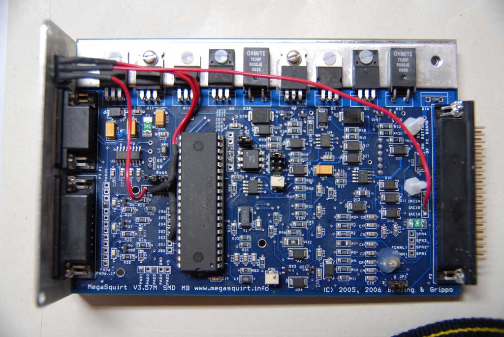
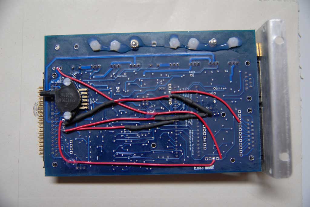
BTW - I renew my request - has anyone a pic of the Miata mods on a 3.57 board? That would help me a lot to confirm what I have to do...
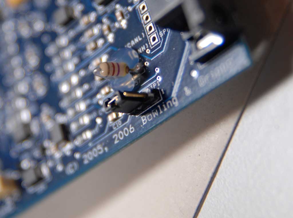
Here are some pics of the board and the resistor sitting at R57
-----------------------
Edit:
Is it correct, that the mod would look like this? (And of course removing the resistor at R57)
Greets
BTW - I renew my request - has anyone a pic of the Miata mods on a 3.57 board? That would help me a lot to confirm what I have to do...
Here are some pics of the board and the resistor sitting at R57
-----------------------
Edit:
Is it correct, that the mod would look like this? (And of course removing the resistor at R57)
Greets
Last edited by Zaphod; 10-04-2008 at 04:18 AM.
Reply
0
0
10-04-2008, 12:40 PM
#17
Boost Pope
iTrader: (8)
Join Date: Sep 2005
Location: Chicago. (The less-murder part.)
Posts: 33,015
Total Cats: 6,587
Well - that looks like Fedor Dostojevsky in his best times to me - wait... no.. I can read Russian way better than this
BTW - I renew my request - has anyone a pic of the Miata mods on a 3.57 board? That would help me a lot to confirm what I have to do...
However your pictures are entirely adequate. From them, I can see that the secondary trigger input has been set up correctly, as well as the two spark outputs and your modifications for knock sensing and table switching inputs.
Also, you are correct in how you have drawn the pullup for the primary input from S12C to JP1, with the 470 ohm resistor in series.
Reply
0
0
10-04-2008, 01:10 PM
#18
Elite Member
Thread Starter
Join Date: Mar 2006
Location: Schwarzenberg, Germany
Posts: 1,553
Total Cats: 101
Is it right, that it doesn't matter in which direction the resistor is mounted? Banded end to S12 or to JP1?
Any other thoughts to the resistor at R57? It looks nearly like the 470ohm I bought.
Thanks
Sven
Any other thoughts to the resistor at R57? It looks nearly like the 470ohm I bought.
Thanks
Sven
Reply
0
0
10-05-2008, 11:19 AM
#20
Elite Member
Thread Starter
Join Date: Mar 2006
Location: Schwarzenberg, Germany
Posts: 1,553
Total Cats: 101
O.K. mod is done, R57 removed.
No startup - so, Joe, more food for your binary knowledge...
I attach 2 logs - could you please take a look if anything has changed?
https://www.miataturbo.net/forum/att...1&d=1223220152
https://www.miataturbo.net/forum/att...1&d=1223220152
Edit:
Hi, I just add another question - supposing Jasons circuit works and everything else seemed fine.
Maybe the timing is completly off and thats why there is no way to start the car. How do I check the timing without the car running?
I doesn't start with the oem ignition as well as ignition from MS. Car starts with oem ecu (bad because of the big 460cc injectors, but it runs)
Thanks,
Sven
Last edited by Zaphod; 10-05-2008 at 12:16 PM.
Reply
0
0


