When you click on links to various merchants on this site and make a purchase, this can result in this site earning a commission. Affiliate programs and affiliations include, but are not limited to, the eBay Partner Network.
So I should use pin 28 of the MS3X connector for VSS and not pin 29, correct?
if Pin 28 is tableswitching, then yes. Nitrous IN wont work for the VSS input (or almost anything else for that matter).
The wiring diagram is good, but we all used images of connectors that are "mirrored" or backwards or whatever. I'm working on correcting that.
tables do nothing for me, im not even going to look at it, cause i know that visual image of the connector and the wires is correct -- so no need to reinvent the wheel. When you build the harness, are you going to want to look at a diagram or a table?
I totally understand you wanna get this right.
Another thing you can add is another spare INJ output to your CEL light. otherwise i think youre all set.
I still find this the best way to do the wiring. Everything is inside the case and plug and play. Don't understand why people find it silly.
It's actually slick and clever, i just dont like how crammed it is, and unflexible it is. Like let's say i had to swap out the expander card for some unknown reason -- that's a lot of effort removing it now (instead of [1] wire attached).
It's actually slick and clever, i just dont like how crammed it is, and unflexible it is. Like let's say i had to swap out the expander card for some unknown reason -- that's a lot of effort removing it now (instead of [1] wire attached).
That's my only issue with it. It is really really hard to add any sort of expansion, or extra cards inside.
Anybody want an ms3? Has lots of features and pre wired for my specific harness
To each their own I guess. I much preferred the table I made when building it. I could then just cross reference the number/letter combo to the connector, but whatever it's just semantics. The flipped around mirrored image whatever confused the hell outta me looking at it for the first time. Plus it was like 11PM...
So now I am done with the harness. Here it is installed in the car:
So now I have to take that beautifully wrapped kapton tape off to run the INJ circuit for the CEL.
Which board's INJ circuit are we dealing with here? I assume MS3X, in which case the only one left is INJ E on pin 7.
Which number/letter combo on the miata connector goes to the CEL light?
On a separate note, I would like someone to confirm that this is the correct setup for pinning the GM AIT sensor into the stock 97 connector.
I also have a question about where I should tap the +12v for the MTXL. Looks like people say the blue wire under the dash from the ignition switch but i'd like to see what you all say.
The rest of the wires go as described, right?
WHITE dimming wire will just be grounded to the body somewhere for now.
BLACK Engine grounding wire for the MTXL goes through the firewall and onto the fuel rail ground bolt.
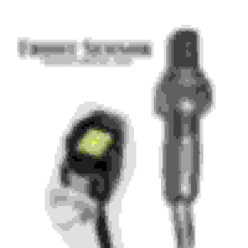
YELLOW wideband wire goes through the firewall and into the signal pin of O2 connector. I'm having trouble figuring out which one is the signal pin. Looks like there are 4 pins.
I'm planning on taking out the front O2 sensor and using it's bung for the wideband. I'll just disconnect the rear O2 sensor from the harness. This sound reasonable to you all?
for O2 signal, its the OEM NB wire on your harness. just use that since you wont use/need the stock sensor. For the power, i used the white/red that powers the ecu. That way the sensor stays powered up during cranking and doesnt go through the heating stage multiple times.
Ok that makes sense. Is it a good idea to use one of the megasquirt grounds for the wideband? Seems like I could just tap into one of the chassis ground wires on the harness I just made. Although I wonder if running power through the board for this thing is a good idea anyway, considering the heater draws 3 amps. Where do you run your ground Jesse?
Back to the CEL question. I found this thread:
https://www.miataturbo.net/megasquirt-18/ms-wiring-questions-fan-control-cel-74024/
He discusses oil sensors and CEL, but he had a 90-93 and I saw no mention of pinouts of where exactly the CEL light goes to the ECU. I just need to figure out where on the OEM harness the damn bulb runs to... I'd rather not have to pull the dash and break out the continuity tester just to find out.
I find it hilarious that you use your computer to log into an internet forum to bitch about having to physically trace a wire in a car for which schematics are plentiful.
You know if you guys really get this assravaged about normies invading your board, why do you even bother replying? Or even coming here at all? Just sage and move on.
That is, unless you ENJOY bitching about me bitching about a wire...
You know if you guys really get this assravaged about normies invading your board, why do you even bother replying? Or even coming here at all? Just sage and move on.
That is, unless you ENJOY bitching about me bitching about a wire...
we can only spoonfeed so much until we run out of baby food...
Ok that makes sense. Is it a good idea to use one of the megasquirt grounds for the wideband? Seems like I could just tap into one of the chassis ground wires on the harness I just made. Although I wonder if running power through the board for this thing is a good idea anyway, considering the heater draws 3 amps. Where do you run your ground Jesse?
do not wire your WBo2 FROM the MS, wire it using the wires leading up TO the MS. The main power and ground at your harness is the best place. Always use (white/red) power wires. Why in the world would you want the MS to provide the power?
i use the white/red wire in the harness that FEEDS the MS and one of the grounds that FEEDS the MS. I foget which one exactly i used. Either 2A or 2B on my 93.
Got it to idle on the first crank. AFR is around 9.5 and my advance was ~ 7 degrees.
I can't tell if it was that rich because of the warm up enrichment table or because of the base map itself. It was like 45* F outside at 4 AM and my friend and I couldn't feel our toes, so we called it quits for now. I threw the stock ECU in and went home.
Does anybody have an MSQ file that will work for the latest version of tunerstudio? I found a few but they seemed not to play well when I loaded them in because they were out of date or something.
do not wire your WBo2 FROM the MS, wire it using the wires leading up TO the MS. The main power and ground at your harness is the best place. Always use (white/red) power wires. Why in the world would you want the MS to provide the power?
I ended up running +12v from the car's harness (white/red), and then I ran the ground straight to the head. I spliced the dimming wire into the rear running light power. It all works.
As for the O2 signal wire, I ran both the wideband and narrowband outputs to a 2 position switch I mounted in the dash, and then ran the switch output to my harness O2 signal wire. I can now switch freely from wideband to narrowband for swapping my ECU on the fly.
Conversion from megasquirt to OEM takes around 4 minutes on my naturally aspirated setup.
It's better to ground it as close to the ECU as possible to remove any grounding offsets between the wideband ground and ecu ground. Im sure you notice the MS's AFR gauge doesnt quite match your wideband controller's own.
why did you run a switch? your wbo2 has two outputs -- one can send a linear 0-5v, the other can mimic a 0-1v narrowband.
 12-16-2016, 07:43 AM


 0
0