AIT wiring question
 11-10-2013, 03:09 PM
#1
Senior Member
Thread Starter
iTrader: (4)

Join Date: Jul 2006
Location: Shelton, CT
Posts: 675
Total Cats: 2
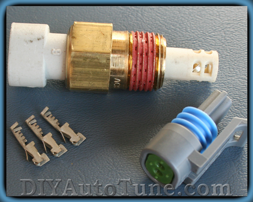
Okay, so I have the AIT sensor kit and bung from DIY.
I'm looking at the instructions for installing things and it describes two wires going into the AFM connector, but I seem to have only one that came in the kit. Also, since the sensor wires are not connected on either end I'm not sure which wires go where.
I'm looking at the instructions for installing things and it describes two wires going into the AFM connector, but I seem to have only one that came in the kit. Also, since the sensor wires are not connected on either end I'm not sure which wires go where.

Reply
 0
0

0
11-10-2013, 03:25 PM
#2

huh?
You said AFM so I'm assuming you have a 90-93. This is pulled from Reverents instructions for installing a MS.
Just splice the wires, or use a spade connector, and extend those two wires to the wires on the end of the IAT pigtail (which is a red and a black I think). No polarity so it doesn't matter which to which.
Hope that helps.
You said AFM so I'm assuming you have a 90-93. This is pulled from Reverents instructions for installing a MS.
On the US 90-93 1.6L (and European 94-97 1.6L), the GM sensor replaces the
sensor that is inside the AFM (Air Flow Meter). Disconnect the AFM, and pull
back the rubber boot of the AFM's connector. You should see 7 wires on it. The
GM IAT connects to the red/green and black/green wires. No polarity.
sensor that is inside the AFM (Air Flow Meter). Disconnect the AFM, and pull
back the rubber boot of the AFM's connector. You should see 7 wires on it. The
GM IAT connects to the red/green and black/green wires. No polarity.
Hope that helps.
Reply
0
0
11-10-2013, 03:34 PM
#3
Senior Member
Thread Starter
iTrader: (4)
Join Date: Jul 2006
Location: Shelton, CT
Posts: 675
Total Cats: 2
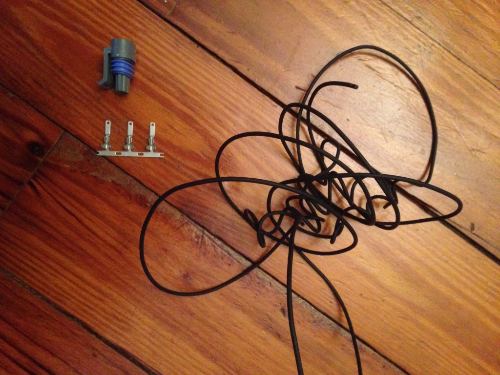
No, the point is that I have one wire in the kit and I seem to need two. There is no IAT pigtail with what I got. I got the IAT, the connector without any wires attached, and one wire. It seems like I need two wires coming off the IAT.
Reply
0
0
 11-10-2013, 03:44 PM
#5
Senior Member
Thread Starter
iTrader: (4)
Join Date: Jul 2006
Location: Shelton, CT
Posts: 675
Total Cats: 2
The other problem I have is how does this work?
The connector that goes into the sensor itself is obviously not hooked up to any wires. How does this come together? Those three tabs obviously came with the kit so I'm assuming they go into the connector, not sure exactly how though.
Reply
0
0
 11-10-2013, 03:57 PM
#9
Senior Member
Thread Starter
iTrader: (4)
Join Date: Jul 2006
Location: Shelton, CT
Posts: 675
Total Cats: 2
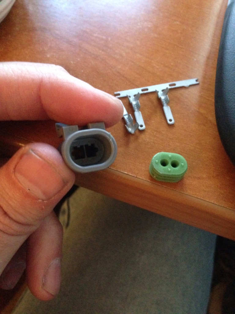
I'm assuming one removes the back of the connector like I have in the pic, sticks the wires through the green plastic portion and then attaches them to the pin that then goes into the connector with the long flat side first?
I'm assuming that I crimp some portion of the metal piece, but I'm not sure which. Or do I just run the wire into the hole on the end?
Reply
0
0
11-10-2013, 04:01 PM
#13
Senior Member
Thread Starter
iTrader: (4)
Join Date: Jul 2006
Location: Shelton, CT
Posts: 675
Total Cats: 2
I'm sorry! It did seem obvious, but damned if I haven't made mistakes before. It's also not exactly plug and play. The orientation of the thing and how it is supposed to go in is not obvious. Is there any necessity for it to go in a certain way?
Reply
0
0
11-10-2013, 05:39 PM
#16

Those crimp pins don't look like the correct ones for that connector (see if the pins actually mate up with the pins on the sensor). I believe the pins should be female.
Also, for this particular connector (GM IAT), you put the wires through the rubber seal, then through the connector. Then you crimp on the pins and pull the wires back. The pins snap in from the front of the connector, not the rear.
--Ferdi
Also, for this particular connector (GM IAT), you put the wires through the rubber seal, then through the connector. Then you crimp on the pins and pull the wires back. The pins snap in from the front of the connector, not the rear.
--Ferdi
Reply
0
0
11-10-2013, 06:00 PM
#17
Senior Member
Thread Starter
iTrader: (4)
Join Date: Jul 2006
Location: Shelton, CT
Posts: 675
Total Cats: 2
This is kinda what I was asking, it doesn't seem obvious how the damned thing is supposed to work.
It doesn't look like the connectors really fit very well either way. I ended up crimping the wires on and putting them in through the back of the connector (after putting the wires through the rubber) with the tab part sticking into the front. I have no clue if this is right or not.
I kinda wish the kit had come with a pigtail connector.
Reply
0
0