DIYPNP install: inital tuning
 05-12-2011, 12:42 PM
#181
Elite Member

Join Date: Jul 2005
Posts: 6,420
Total Cats: 84
D allows more P without oscillation. And D will drive duty% based on the slope of RPM. So when RPM *begins* to drop (before it has dropped far), D will drive duty% up. P will only raise duty% in proportion to how far RPM has dropped. IOW P will max when RPM has bottomed. D, OTOH, maxes when the RPM drop is steepest... before RPM bottoms.
I is just a long term correction.

Reply
 0
0

0
05-12-2011, 12:47 PM
#182

That's a good link.
FWIW
The bottom figure on page 1, figure 9-4, is the boost control architecture I recommend. A 3D lookup table (duty% output, vs. boost target vs. RPM) would provide the feed-forward. The difference is that an error derivative works better than a target derivative. (full PID on the error signal, not just PI)
Page 2 on error band limits, needs to be applied to the I output - in order to limit it within a certain range to prevent windup problems. The I output in boost control only needs to address the remaining error, which can come from variations in ambient temperature and altitude.
Such a system would have the 3D lookup table instantly predict the necessary duty% for the target boost, then the PID is for fast response.
For TPS controlled boost, the boost target should be a 3D function of RPM and TPS.
My AEM setup with a custom D circuit, resembles the above architecture. (AEM has no D anywhere)
Lastly an autotuning algorithm that fills in the feedforward 3D table, would be baller. This is how OEMs do it.
Reply
0
0
05-12-2011, 07:15 PM
#183
Junior Member
Thread Starter

Join Date: Jun 2007
Posts: 411
Total Cats: 0

So for cases of big fast rpm drops, d should be the predominant response!? It will max when the drop is steepest, and also taper off before the bottom.
So D is not directly a damper to P, meaning it doesn't react to P's actions per se. It has it's own reactions to a step change, which if tuned correctly, also act in a way that dampens P (since P's actions affect the step change). So a pid of 0/0/200 will still have some action. Did I get that right?
Last edited by Greg G; 05-12-2011 at 09:44 PM.
Reply
0
0
05-13-2011, 12:04 AM
#184
Elite Member
Join Date: Jul 2005
Posts: 6,420
Total Cats: 84
D does not react to P's actions. It allows more P because it prevents the *system* oscillation that would otherwise occur, by reacting "earlier" than P. It reacts to the slope of the error, and so it also prevents overshoot by "braking" the duty% if the target is approached too fast. As the target is approached, P diminishes, and if it is approaching fast, you get a large duty% reduction from D, to slow it down as it approaches.
Reply
0
0
05-13-2011, 10:34 PM
#186
Junior Member
Thread Starter
Join Date: Jun 2007
Posts: 411
Total Cats: 0
As advised by Ken, I edited the .ini file to change the maximum allowable D. I made it 1600 from 200 
So here goes!
p40i12d200
p42i12d600 (ghost p42i12d600)
p40i12d800
p10i5d1600
p20i5d1600
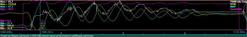
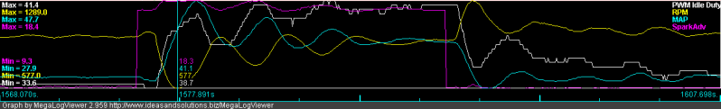
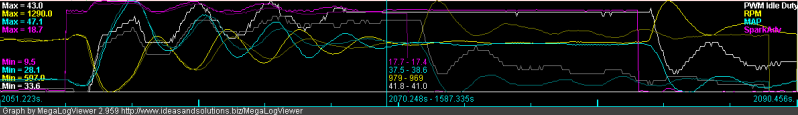
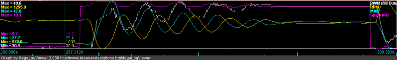
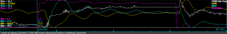
I think 1600 is too much D. It doesn't allow me to add too much P--effect of low P is: the maximum droop ends up lower.
Dialed it down to 800 D and retuned:
p35i10d800
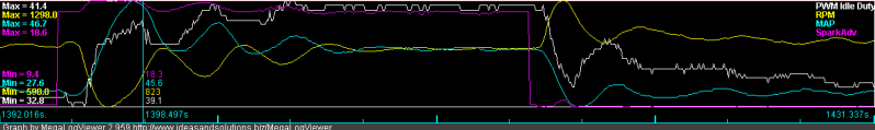
p35i10d800 vs (ghost) p42i12d600
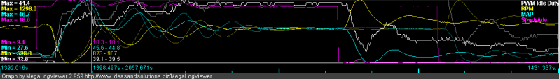
Sweet spot (at least to me) is somewhere around 800 D. Maybe a little more...? Increasing the D value has shifted the PWM idle valve duty sinusoid to the left a little (unless I'm imagining it), and does show a "firmer damping" of the P action at the peaks and troughs of the RPM sinusoid. I may need to reduce hysteresis (narrow the target rpm range), since the closed loop algorithm seems to be controlling the oscillations more tightly.
Now to chew on the data.
So here goes!
p40i12d200
p42i12d600 (ghost p42i12d600)
p40i12d800
p10i5d1600
p20i5d1600
I think 1600 is too much D. It doesn't allow me to add too much P--effect of low P is: the maximum droop ends up lower.
Dialed it down to 800 D and retuned:
p35i10d800
p35i10d800 vs (ghost) p42i12d600
Sweet spot (at least to me) is somewhere around 800 D. Maybe a little more...? Increasing the D value has shifted the PWM idle valve duty sinusoid to the left a little (unless I'm imagining it), and does show a "firmer damping" of the P action at the peaks and troughs of the RPM sinusoid. I may need to reduce hysteresis (narrow the target rpm range), since the closed loop algorithm seems to be controlling the oscillations more tightly.
Now to chew on the data.
Last edited by Greg G; 05-14-2011 at 02:26 AM.
Reply
0
0


 05-15-2011, 07:58 PM
#191
Junior Member
Thread Starter
Join Date: Jun 2007
Posts: 411
Total Cats: 0
No idea what it means, but here's the relevant part:
/* Convert the rpms to generic percents in % * 10000 units.
* Avoid going below the min rpm set by the user.
* That will cause a large duty cycle spike
*/
rpm = outpc.rpm;
if (rpm < flash5.pwmidle_min_rpm) {
rpm = flash5.pwmidle_min_rpm;
}
PV = ((long)(rpm - flash5.pwmidle_min_rpm) * 10000) /
(flash5.pwmidle_max_rpm - flash5.pwmidle_min_rpm);
SP = ((long)(targ_rpm - flash5.pwmidle_min_rpm) * 10000) /
(flash5.pwmidle_max_rpm - flash5.pwmidle_min_rpm);
if ((pwmidle_reset == PWMIDLE_RESET_CALCNEWTARG) ||
(pwmidle_reset == PWMIDLE_RESET_JUSTCRANKED)) {
PV_last[0] = PV_last[1] = PV;
}
rpm_error = PV - SP;
pwmidle_deriv = PV - (2*PV_last[0]) + PV_last[1];
/* don't divide these down (I'm using them as percents)
* to help get better resolution in the next calcs
*/
Kp = ((long)((PV - PV_last[0]) * flash5.pwmidle_Kp));
Ki = ((((long)rpm_error * flash5.pwmidle_ms) / 1000) * flash5.pwmidle_Ki);
Kd = ((long)pwmidle_deriv * (((long)flash5.pwmidle_Kd*10)/flash5.pwmidle_ms));
PV_last[1] = PV_last[0];
PV_last[0] = PV;
/* now that we have the raw values in percent to change the output by, we need
* to convert it down to the actual output's units.
* To do that we multiply by the open duty - the closed duty, and divide that by
* 100 (cross multiply).
*/
Reply
0
0
05-16-2011, 02:10 AM
#192
Elite Member
Join Date: Jul 2005
Posts: 6,420
Total Cats: 84
I see, Kp, Ki, and Kd are actually dKp, dKi, and dKd (derivatives), which are used as addends to the current duty%, instead of directly calculating duty%.
The line
pwmidle_deriv = PV - (2*PV_last[0]) + PV_last[1];
is the 2nd derivative.
The usual
CO = - (Kp*E + Kd*dE/dt + Ki*integral(E) )
got differentiated on both sides to get
CO -= (Kp*dE + Kd*d^2E + Ki*E)
It seems to make sense, but with the disadvantage that the D output kicks in 2 ticks after the RPM begins to drop. If sampling rate is 100 ms then there is a 200 ms delay in the effect of D. Then D can't be used for oscillations faster than about 1 Hz or so. HST, Greg's oscillation appears to be slower than that.
If the above delay is a problem there's a way around it, which is to process D in the old fashioned way. That would reduce the delay in D to 1 tick.
Can I see the code after the above snippet? Maybe there's an error in the sign there, e.g.
COnew = COold - Kp*dE + Kd*d^2E - Ki*E
Reply
0
0
05-16-2011, 06:54 AM
#193
Junior Member
Thread Starter
Join Date: Jun 2007
Posts: 411
Total Cats: 0
A 200 ms delay is huge for me! In the first 200 ms from AC engagement, the rpm drops 200 rpm with no appreciable increase in idle valve duty. So if that delay can be reduced even by half, the droop may be significantly reduced. And if the phase shifting can be implemented, that may just solve everything!
Well that and an idle duty % adder triggered by PE1. That will lessen the initial droop that closed loop idle has to deal with in the first place
Crosses fingers...
Well that and an idle duty % adder triggered by PE1. That will lessen the initial droop that closed loop idle has to deal with in the first place
Crosses fingers...
Reply
0
0
05-28-2011, 06:53 AM
#194
Junior Member
Thread Starter
Join Date: Jun 2007
Posts: 411
Total Cats: 0
Reposting from Msextra, to keep the discussion updated:
I leave the D discussion for others to discuss 
I is a sad kitty 
I did notice this, though-- I had one episode of a really good AC engagement, while WUE was on, CLT 120. 200 rpm droop, resolved with 2 small oscillations! A fluke? Still with the PID of 35/10/800. Taking off from this, I will try switching VE tables with a richer idle, to keep the afr consistent with and without AC. Wondering if it's the higher RPM target, richer AFR, or the higher advance (less MAT based retard)...
Yeah, I just double checked, and there's no error in the sign on the D-term.
The D term is not coupled to error in the idle speed control loop, it's only coupled to change in RPM, which changes the sign you need to use to get the proper behavior.
But essentially if you want "instant" response to the droop, the P term is what you want to change, and you can help there with idle advance (add advance when AC engages) and by adding a little fuel when AC engages.
Ken
I wasn't planning on adding the hardware trigger to ms2.
Ken
Ken
I did notice this, though-- I had one episode of a really good AC engagement, while WUE was on, CLT 120. 200 rpm droop, resolved with 2 small oscillations! A fluke? Still with the PID of 35/10/800. Taking off from this, I will try switching VE tables with a richer idle, to keep the afr consistent with and without AC. Wondering if it's the higher RPM target, richer AFR, or the higher advance (less MAT based retard)...
Last edited by Greg G; 05-28-2011 at 08:51 AM.
Reply
0
0
05-29-2011, 07:12 PM
#199
Junior Member
Thread Starter
Join Date: Jun 2007
Posts: 411
Total Cats: 0
Nope, I think it's not possible. I tried editing the ini file to change the minimum value from zero to -1600.
Now if I enter a negative value, the D value becomes some crazy positive value! For example entering -1 into the box-- the number changes to 6552.6; entering -800, the number changes to 5753!
Well, at least now we know that's not the way to go...
Now if I enter a negative value, the D value becomes some crazy positive value! For example entering -1 into the box-- the number changes to 6552.6; entering -800, the number changes to 5753!
Well, at least now we know that's not the way to go...
Reply
0
0
05-29-2011, 07:55 PM
#200
Elite Member
Join Date: Jul 2005
Posts: 6,420
Total Cats: 84
What Ken said, "The D term is not coupled to error in the idle speed control loop, it's only coupled to change in RPM, which changes the sign you need to use to get the proper behavior." suggests that the code needs to be modified then, so that the sign is inverted, to get the proper behaviour.
Reply
0
0


