DIYPNP install: inital tuning
 05-08-2011, 08:50 AM
#161
Junior Member

Join Date: May 2007
Location: Columbia, MD
Posts: 248
Total Cats: 0
Usually when I see that sort of oscillation, it is due to factors other than idle valve control. For example, no amout of PID tuning will get rid of oscillation caused by ignition timing changes or AFR changes. Assuming you already checked that, Jason's advice in this case is good. Reducing the rpm range will make the algorithm more sensitive.
You may also want to try the latest changes that mariob has made. He improved the precision of the stored duty from previous iterations of the PID loop and the associated addition. Those changes require a retune, but they do make a pretty big difference in the responsiveness of the loop.
There is a thread over at msextra about it. He also made changes to the duty used at each entry to the loop (after throttle lift) so that it uses both the "last good" value and the open loop warmup-only value (averages the two I believe). So if you use his code you'll have to tune that as well.
Ken

Reply
 0
0

0
05-08-2011, 09:50 AM
#162
Junior Member
Thread Starter

Join Date: Jun 2007
Posts: 411
Total Cats: 0
Hi Ken,
The AFR and spark timing are as flat as I can get em. I am already using the latest '3.1.1 mariob v5' firmware. I will reduce the rpm range and retune.
Was hoping I could convince you to add a % adder to the idle duty, triggered by PE1. That'll give me (and others) some sort of proactive control, as opposed to a reactive response. Backport from MS3?
Greg
Reply
0
0
05-11-2011, 06:42 AM
#163
Junior Member
Thread Starter
Join Date: Jun 2007
Posts: 411
Total Cats: 0
I reduced the RPM range from 600-1800 to 700-1500. The closed loop response did become more sensitive! I had to reduce P and I.
Current settings: PID 40/12/200
Old (ghost) settings: PID 80/20/200
Another difference is that I re-enabled the idle advance, spiking the timing up when RPM dips below 850. I turned it off after I went with table switching, but I realized it might be useful as added support, only for large droops. I think I might reduce the trigger rpm to 800. Still deciding if using idle advance in this way helps, or upsets the system even more...
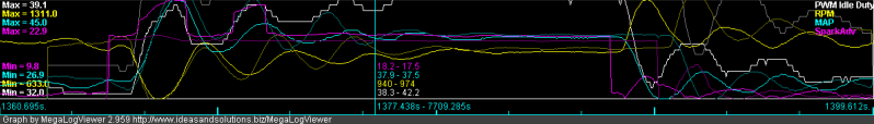
Almost the same. The maximum droop does seem to be decreased by about 50 rpm less. Not dropping below 600 anymore. The oscillations appear to have less amplitude (?) I guess that's progress...
Current settings: PID 40/12/200
Old (ghost) settings: PID 80/20/200
Another difference is that I re-enabled the idle advance, spiking the timing up when RPM dips below 850. I turned it off after I went with table switching, but I realized it might be useful as added support, only for large droops. I think I might reduce the trigger rpm to 800. Still deciding if using idle advance in this way helps, or upsets the system even more...
Almost the same. The maximum droop does seem to be decreased by about 50 rpm less. Not dropping below 600 anymore. The oscillations appear to have less amplitude (?) I guess that's progress...
Last edited by Greg G; 05-11-2011 at 10:04 AM.
Reply
0
0
05-11-2011, 11:26 AM
#164
Elite Member

Join Date: Jul 2005
Posts: 6,420
Total Cats: 84
Still no meaningful D action.
Maybe the max D gain value of 200 still isn't enough, in the code. Maybe it's stunted. Maybe the code "filters" the D output, inadvertently neutralizing its action. Or maybe it needs an extra multiplier, e.g. if the user puts in "30", the code will multiply by 10 and thus use 300.
Because the D output is supposed to be proportional to the *slope* of the RPM, looking at the first RPM dip, D should peak the duty% *as* the RPM is dropping, *before* RPM bottoms. Instead duty% peaks at the same time as RPM bottoms. This is purely P action.
And then, if it's oscillating, the D term should cause the duty% sinusoids to "lead" the RPM sinusoids. IOW the duty% should not merely look like a mirror-in-the-pond image of RPM - that's what P does. Added D should make the duty% sinusoids to appear to "shift left" relative to where it is now.
Without D, large P will cause oscillation. The P action is "too late" without D. D effectively makes the loop's reaction earlier.
P and D should be tuned together, as they work together.
Last edited by JasonC SBB; 05-11-2011 at 12:39 PM.
Reply
0
0
05-11-2011, 12:00 PM
#165
Elite Member
Join Date: Jul 2005
Posts: 6,420
Total Cats: 84
Below are simple simulations of a feedback loop with
1) no D,
2) some D, and
3) big D.
They all have a fixed P.
In the first one you will see that the duty% peaks at the same time as the RPM bottoms. And in the subsequent sinusoids, the duty% is a mirror image of the RPM:

In the 2nd one, with some D, you will see that the duty% peaks *before* the RPM bottoms. And in the sinusoids, the duty% is also a mirror, *but* shifted a bit left. Oscillations are a bit damped too, because the D causes the duty% to "react" a bit earlier. This is what I meant by D being "anticipatory":
In the 3rd one, with aggressive D, you will see that the duty% peaks very strongly, and the response is completely damped:
Note that more D also reduces the depth of the RPM dip.
1) no D,
2) some D, and
3) big D.
They all have a fixed P.
In the first one you will see that the duty% peaks at the same time as the RPM bottoms. And in the subsequent sinusoids, the duty% is a mirror image of the RPM:
In the 2nd one, with some D, you will see that the duty% peaks *before* the RPM bottoms. And in the sinusoids, the duty% is also a mirror, *but* shifted a bit left. Oscillations are a bit damped too, because the D causes the duty% to "react" a bit earlier. This is what I meant by D being "anticipatory":
In the 3rd one, with aggressive D, you will see that the duty% peaks very strongly, and the response is completely damped:
Note that more D also reduces the depth of the RPM dip.
Last edited by JasonC SBB; 05-11-2011 at 12:25 PM.
Reply
0
0
 05-11-2011, 12:37 PM
#169

There's got to be a ratio between P and D or I and D when the P and I are tuned correctly.
My PID values are 1.8, 5.0, and 1.5 respectively. I think I could use slightly more D. It works extremely well. Something causes an occasional instability at idle that has to be corrected. It is a change in AFR that sets it off. It's almost like the car misses at idle.
This is with timing
timing
40kpa 20 11 10
30kpa 20 11 19
20kpa 22 22 23
rpm 500 950 1500
Reply
0
0
05-11-2011, 12:44 PM
#170
Boost Czar


iTrader: (62)
Join Date: May 2005
Location: Chantilly, VA
Posts: 79,493
Total Cats: 4,080
P doesn't find the target, I does.
P is the spring, D is the damper.
I targets and tracks.
more P will react faster to any random load changes, and more D will prevent it from overshooting.
I'm fairly happy with 20 | 17 | 40. YMMV.
P is the spring, D is the damper.
I targets and tracks.
more P will react faster to any random load changes, and more D will prevent it from overshooting.
I'm fairly happy with 20 | 17 | 40. YMMV.
Reply
0
0
05-11-2011, 01:14 PM
#172
Junior Member
Thread Starter
Join Date: Jun 2007
Posts: 411
Total Cats: 0
I hope Ken doesn't mind my reposting his response on MSExtra here. Helps the flow of discussion 
Re: Idle tuning for AC load: Mazda Miata
Postby muythaibxr � Thu May 12, 2011 2:00 am
I do divide down the output of the D term a bit, and it's possible that I did so too much.
I can probably send a test code that divides that down less, or in the meantime, you can edit the ini file yourself and change the max allowed D value to a higher number.
To be honest I've never needed any D term on the stuff I've tuned though. Not for idle anyway. Boost and EGO I've seen need for it though.
I do damp the D response down a bit based on the control interval though. Longer interval means more damping.
Ken
Reply
0
0
05-11-2011, 08:30 PM
#175
Junior Member
Thread Starter
Join Date: Jun 2007
Posts: 411
Total Cats: 0
 ), this is how I understand it:
More P will drive the idle valve duty faster. This must be controlled by D. Since D is apparently damped (dampened damper), this is the rate limiting step, in my application. With maximum allowed D, I can only run moderate P.
The reason I have to run these aggressive settings is because of the large throttled volume of the supercharger. The stock throttle body is relocated to the hotside, so the idle valve sees the volume of that entire tract from the supercharger to the intercooler, and the intake manifold, instead of just the volume of the intake manifold. The idle valve has to fill up that space, and that "filling time" is probably the reason the reaction to the dip is damped/absorbed. Solutions are to drive the duty faster/harder, add a second air solenoid to help fill that volume, or reduce that throttled volume- the dual throttle mod.
I is just a long term correction. I do notice that I find the best combinations of PID have roughly a 4:1 P:I ratio. In my car at least. YMMV.
Last edited by Greg G; 05-11-2011 at 08:56 PM.
Reply
0
0
05-12-2011, 04:04 AM
#176
Elite Member
iTrader: (1)

Join Date: Jun 2006
Location: Warrington/Birmingham
Posts: 2,642
Total Cats: 42
Cant offer any help in tuning, but I have to say this is the most interesting thread I've read on MegaSquirt tuning in a very long time, great work Greg and Jason.
Reply
0
0

 05-12-2011, 07:36 AM
#178
Elite Member
iTrader: (1)
Join Date: Jun 2006
Location: Warrington/Birmingham
Posts: 2,642
Total Cats: 42
Hell if you can persuade Ken to improve the PID code to how Jason suggest even better for everyone.
A DTB kit will certainly fix your issues, but I personally feel that you should be able to tune these issues out too.
A DTB kit will certainly fix your issues, but I personally feel that you should be able to tune these issues out too.
Reply
0
0
05-12-2011, 07:57 AM
#179
Junior Member
Thread Starter
Join Date: Jun 2007
Posts: 411
Total Cats: 0

Back on topic--this makes for interesting reading...
http://www.eetimes.com/design/indust...ctive-controls
Reply
0
0
05-12-2011, 12:37 PM
#180
Elite Member
Join Date: Jul 2005
Posts: 6,420
Total Cats: 84
That's a good link.
FWIW
The bottom figure on page 1, figure 9-4, is the boost control architecture I recommend. A 3D lookup table (duty% output, vs. boost target vs. RPM) would provide the feed-forward. The difference is that an error derivative works better than a target derivative. (full PID on the error signal, not just PI)
Page 2 on error band limits, needs to be applied to the I output - in order to limit it within a certain range to prevent windup problems. The I output in boost control only needs to address the remaining error, which can come from variations in ambient temperature and altitude.
Such a system would have the 3D lookup table instantly predict the necessary duty% for the target boost, then the PID is for fast response.
For TPS controlled boost, the boost target should be a 3D function of RPM and TPS.
My AEM setup with a custom D circuit, resembles the above architecture. (AEM has no D anywhere)
Lastly an autotuning algorithm that fills in the feedforward 3D table, would be baller. This is how OEMs do it.
Reply
0
0


