DIYPNP with Peak and Hold Driver - Sequential INJ
 05-28-2013, 02:42 PM
#1

I've run out of injectors sooner than I would like. I have some Low Impedance RC Engineering 550cc injectors that are cleaned and tested and want to use them. Since my car is a 93 california car, it is already wired for sequential injection, so I figured I would take advantage. I plan on picking up the Sequential Injection mod for the DIYPNP. How would I wire up JBPerf's Peak & Hold driver to the DIYPNP? I think I could figure it out if I had the parts in front of me, but I want to make sure it's as simple as it seems. Would I pull the inputs for each injector from INJ1 and INJ2 on the microsquirt header and then INJ3 and INJ4 from the add-on board? Would that require grounding the add-on board as if hooking up for low impedance injectors?
Are there any other modifications needed to the board or uS module? I'd like to fully understand the wiring required before purchasing.
Are there any other modifications needed to the board or uS module? I'd like to fully understand the wiring required before purchasing.

Reply
 0
0

0
05-29-2013, 01:33 PM
#2
Supporting Vendor


iTrader: (33)
Join Date: Jul 2006
Location: atlanta-ish
Posts: 12,659
Total Cats: 134
Does the JB Perf P&H board not use *logic* injector triggers? If so, the Microsquirt Module has the logic triggers broken out on its 10 pin header--Alt inj1, Alt inj2, PT6, PT7

Reply
0
0
05-29-2013, 02:46 PM
#3
Boost Pope

iTrader: (8)
Join Date: Sep 2005
Location: Chicago. (The less-murder part.)
Posts: 33,019
Total Cats: 6,587
According to JBs documentation, the inputs are active-low (ground to activate), so it connects to the ECU as though it were a set of injectors.
jbperf.com/p&h_board/index.html
jbperf.com/p&h_board/index.html
Reply
0
0
05-29-2013, 07:33 PM
#4
Supporting Vendor
iTrader: (33)
Join Date: Jul 2006
Location: atlanta-ish
Posts: 12,659
Total Cats: 134
According to JBs documentation, the inputs are active-low (ground to activate), so it connects to the ECU as though it were a set of injectors.
jbperf.com/p&h_board/index.html
jbperf.com/p&h_board/index.html

Reply
0
0
 05-31-2013, 12:31 PM
#7
Supporting Vendor
iTrader: (33)
Join Date: Jul 2006
Location: atlanta-ish
Posts: 12,659
Total Cats: 134
I think you may have been distracted with more pressing business. The board you linked to is clearly driven by the logic level outputs. There are other p&h solutions out there that are triggered by standard ground-level injector outputs.
Reply
0
0
06-08-2013, 06:08 PM
#8
In case anybody else is looking to do the same with their DIYPNP, here is how it has to be mounted:
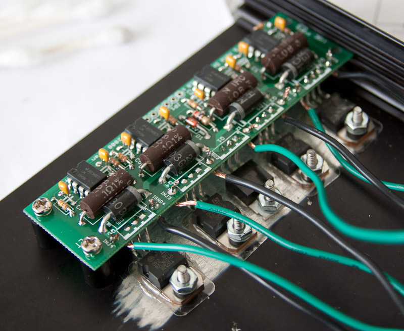
I used 10mm spacers from radioshack and mounted it in the second slot, which isn't ideal. I'd recommend 3/16" spacers and leave it in the bottom slot, but I couldn't find any locally. I didn't realize how much wider the DIYPNP case is than standard MS cases. I also cleaned the paint off and polished the area where the transistors mount for better conduction. The closer to mirror finish, the better the heat transfer. Hopefully mine isn't too unpolished...
I'm also wiring everything into connectors so when I remove the top of the case I can unplug this add-on. I would have finished it today, but I ran out of solder
Reply
0
0

 You serious about that wiring? That's a big

Thread
Thread Starter
Forum
Replies
Last Post
stoves
Suspension, Brakes, Drivetrain
5
04-21-2016 03:00 PM


