Doing MS3x on a stock 91
 11-19-2012, 04:52 PM
#21
Junior Member
Thread Starter

Join Date: Nov 2012
Location: Safety Harbor, FL
Posts: 72
Total Cats: 2
Yeah, but I was wondering if I could rip the harness apart somewhere other than at the fuel rail. If the split is right there, then I have no choice. But, in the unlikely event that the wires actually split somewhere near the ECU... well, that presents different options.
I could always rip things apart and hack away at stuff and ignore the experience of those who have gone before me. I try to avoid that when I can. Saves time, effort, headaches and money.
I could always rip things apart and hack away at stuff and ignore the experience of those who have gone before me.
I try to avoid that when I can. Saves time, effort, headaches and money.

Reply
 0
0

0
11-19-2012, 05:02 PM
#24
Boost Pope


iTrader: (8)
Join Date: Sep 2005
Location: Chicago. (The less-murder part.)
Posts: 33,019
Total Cats: 6,587
Thus, you must run new wiring from the ECU up to the head, and also modify the injector harness itself to bring out the additional injector wires on a new connector.
This is what mine looks like:
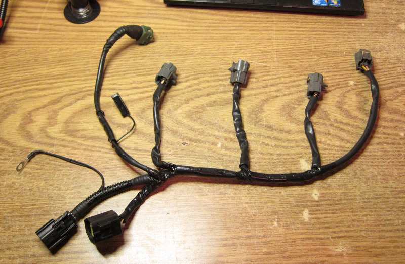
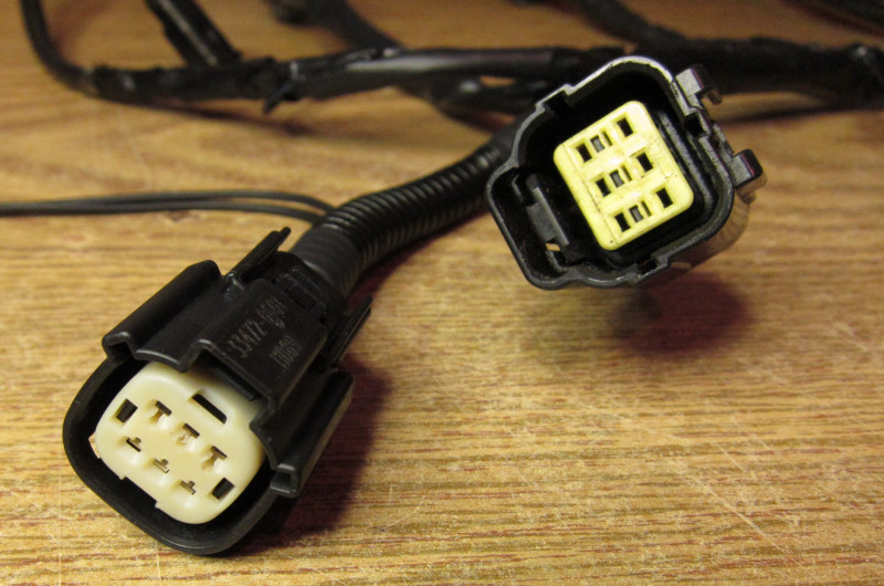
I cut the two injector wires off of the original 6 pin connector, and added an additional six pin connector to carry four discrete injector wires plus two ground wires from the ECU (the ones terminating at the ring connector). This mates with a new harness which I ran through the existing grommet hole in the firewall behind the fuse box (after drilling it oversize).
edit: Beat me to it while I was tracking down the images...
Reply
0
0
11-19-2012, 09:12 PM
#27
Boost Pope
iTrader: (8)
Join Date: Sep 2005
Location: Chicago. (The less-murder part.)
Posts: 33,019
Total Cats: 6,587
Here we go:
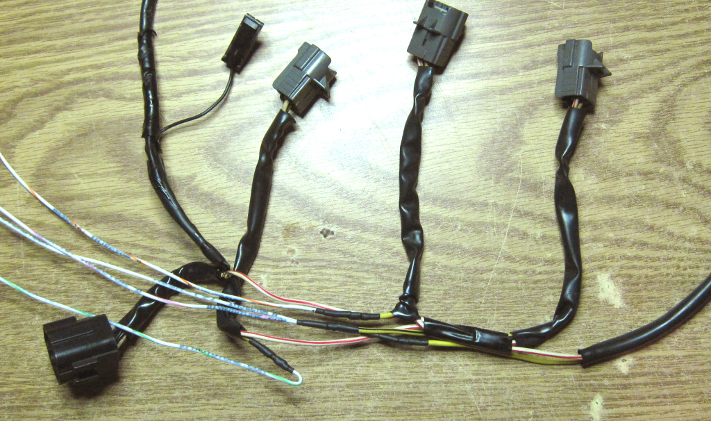
In this photo, I have already severed the two yellow wires at the end of the wrapped portion coming from the stock 6 pin connector, as well as separating the paired yellow wires where they join in the middle between two two sets of injector pigtails. I've then soldered an individual white wire to each of the four (now discrete) yellow injector wires, and brought them out in the same direction as the stock connector. It is these four wires which will be terminated at the new connector, along with the two additional ground lines (these are optional- I just have grounding fetish.)
I left the white/red wire (the 12v supply) untouched.
Reply
0
0
11-20-2012, 08:25 AM
#29
Boost Czar

iTrader: (62)
Join Date: May 2005
Location: Chantilly, VA
Posts: 79,490
Total Cats: 4,079
pretty much exactly what I did too. that extra connector you see in my pics was to be able to revert back to batch, if connected, so I'd still be able to test out any ECUs I built.
This is child's play.
This is child's play.
Reply
0
0
11-23-2012, 12:56 PM
#31
Junior Member
Thread Starter
Join Date: Nov 2012
Location: Safety Harbor, FL
Posts: 72
Total Cats: 2
For the record, should anyone end up here from a search later:
The factory splices are located between injectors 3 and 4 in the factory harness. They are brass crimp splices, and without heat-shrink.
The factory splices are located between injectors 3 and 4 in the factory harness. They are brass crimp splices, and without heat-shrink.
Reply
0
0
11-24-2012, 01:55 AM
#32
Junior Member
Thread Starter
Join Date: Nov 2012
Location: Safety Harbor, FL
Posts: 72
Total Cats: 2
Finally got my MS3x yesterday, but didn't have a lot of time to play with it short of popping it open to inspect the quality of assembly and soldering.
Going to mod the DIYBOB wiring to fit my '91 tomorrow. Doing final planning on that now. Looks like I only need to reposition 4 wires, and add the no-VTPS resistor, then I'll be PnP ready.
I modded the injector harness Thursday and ended up putting the plug on injectors 2 & 3 (so I can remove them from the stock harness, and move them to individual wires). When I started really analyzing this, I realized that batch fire pairs up 1&3 (injA) and 2&4 (injB)... and to keep the injector sequencing correct when going sequential, I need #3 to be on injB. My solution there is to, in addition to switching the connector that gives me 2 additional wires, also switch the connectors on #3 & #4 at the injectors. Net result, original wires feeding #1 (injA) and #3 (injB) and then new wires going to #4 (injC) and #2 (injD).
Does that sound right? Is there an easier way to do it that I'm just not seeing?
I plan to run batch until my WBO2 shows up, I just want to get the wiring on the ECU set up correctly in one shot so that I don't have to mess with it again.
Lastly, unless someone has a better option, I'm going to fire it up on Frank's base 1.6 MSQ. I'll disable EGO (or maybe switch it to NB) since I don't have the wideband yet, otherwise, it appears to be configured correctly for my initial installation.
Reply
0
0
11-24-2012, 03:38 AM
#33
Boost Pope
iTrader: (8)
Join Date: Sep 2005
Location: Chicago. (The less-murder part.)
Posts: 33,019
Total Cats: 6,587
When running fully sequential, the correct wiring is:
INJ-A = Injector 1
INJ-B = Injector 3
INJ-C = Injector 4
INJ-D = Injector 2
Same as the firing order of the engine.
INJ-A = Injector 1
INJ-B = Injector 3
INJ-C = Injector 4
INJ-D = Injector 2
Same as the firing order of the engine.
Reply
0
0
11-24-2012, 03:43 PM
#35
Junior Member
Thread Starter
Join Date: Nov 2012
Location: Safety Harbor, FL
Posts: 72
Total Cats: 2
We have achieved first start!
Trying to figure out idle settings right now... it wants to idle at almost 1200.
AC is inop. Will have to check wiring on that.
Main cooling fan has yet to come on, but that's still triggered by a thermoswitch, right? It's cool today. Engine temp has yet to exceed 195 idling.
Anyway... so far, so good. Just need to learn my way around the new MS3 settings and options.
Reply
0
0
11-24-2012, 08:37 PM
#36
Junior Member
Thread Starter
Join Date: Nov 2012
Location: Safety Harbor, FL
Posts: 72
Total Cats: 2
The idle issue was the idle screw on the TB. Backed it down and the idle is quite nice now. Having fun trying to tune with a NB sensor until my WB shows up next week.
Haven't looked much into the AC problem yet, but found a good thread where Brain explains the ins and outs of it. It all makes sense, just need to figure out what's up.
Tomorrow, I'm going to set REQ FUEL to something reasonable (it was 12.0 by default and has proven to be lean above 4k even at 12.5... and the calculator says it should be 11.8, I think) and then use the NB to try to tune the VE table to stoich. Once I find stoich, I'll add 10% to the top end and interpolate values for the area between there and the cruise area of the table.
Fun stuff!
Reply
0
0
11-25-2012, 12:31 AM
#37
Junior Member
Thread Starter
Join Date: Nov 2012
Location: Safety Harbor, FL
Posts: 72
Total Cats: 2
Cool. I haven't tested it yet, but it looks like my AC isn't wired "wrong", just "different". It's using the N20 switch (29) instead of the Table switch (28), and it's using the N20 output (25) instead of InjG (1). Should work, I just need to set the soft options correctly. And I'll likely never use Nitrous, so no problem there.
I'm diggin' this whole MS3x thing! The configurability is great!
I'm diggin' this whole MS3x thing! The configurability is great!
Reply
0
0
11-26-2012, 03:50 PM
#38
Junior Member
Thread Starter
Join Date: Nov 2012
Location: Safety Harbor, FL
Posts: 72
Total Cats: 2
Still fiddling with the AC and the idle and startup settings. (and probably will be forever) But, I've got the car running really well now, even without a Wideband. I'm not saying that I tuned it with a Narrowband... I made a feeble attempt, but it was a pain.
What I ended up doing was searching around for a good NA MSQ. And, for anyone who is searching in the future, let me throw out some search terms: NA 1.8 1.6 stock megasquirt msq base tune normally aspirated
What I found was a dyno-tuned MSQ for a stock 2000 1.8 making 132 hp at the wheels. (Yeah, dynos lie... whatever. Take 5% off of it and it's still pretty damned good!) It's a 1.8, not a 1.6, but I figured the timing map should be really close, and the fuel map should mostly just need to be scaled.
So, I took those fuel and spark tables, dumped them into my tune. Set the Req Fuel to 12.3 rather than the 12.8 from the 1.8 MSQ. I did have to tweak the timing at idle a little bit. But, otherwise, the car ran fine. Better than fine. And surely better than I'd get it trying to tune with a narrowband sensor.
Before I forget, here's the thread with the MSQ that I stole:
https://www.miataturbo.net/megasquir...o-sheet-67115/
Pretty happy for now... waiting for my WB...
Reply
0
0
11-26-2012, 04:34 PM
#39
Boost Czar
iTrader: (62)
Join Date: May 2005
Location: Chantilly, VA
Posts: 79,490
Total Cats: 4,079
why didn't you use the 90-93 specific MS3x basemap on Frank's website that I gave him that matches the wiring diagram I made as well?
If you load the map I made, it's 85% of the way there and all you have to do is put in your req_fuel and then tune fuel.
running random basemaps for different model MSes and different model year miatas is silly at best.
If you load the map I made, it's 85% of the way there and all you have to do is put in your req_fuel and then tune fuel.
running random basemaps for different model MSes and different model year miatas is silly at best.
Reply
0
0
11-26-2012, 05:19 PM
#40
Junior Member
Thread Starter
Join Date: Nov 2012
Location: Safety Harbor, FL
Posts: 72
Total Cats: 2
Silly though it might be, it worked way better than Frank's map. Don't know why. Frank's MSQ started and idled well, but flat out would not run no matter what I did with the Req Fuel. Regardless, it's running now and running well. (well enough until I get the WB installed)
(digression: The biggest difference I noticed between the two tunes is the timing map. The dyno tuned non-turbo 1.8 map is about 10 degrees more advanced at/near/below 100kPa above 4-5k. My theory is that because you guys are tuning on turbo cars... you're never at 100kPa at those kinds of RPM. You'd be in boost by then and having fun in some other part of the table.)
BUT, I have a question.
I just spent some time out in the driveway fiddling with idle settings and the AC and damn if that's not some weird ****!
I verified that the main fan control is working. It's output is on Nitrous1 and it works as-advertised.
The AC output is wired to Nitrous2. For kicks, I put that output on the main fan to test it. That OUTPUT works as advertised. Fans and AC both come on when commanded in that configuration.
So, I went back to AC settings. The AC switch is wired to Nitrous In. I set the AC output to Nitrous2. This should work. (of course, it doesn't)
What's weird is this:
First, I figured out that it was working BACKWARDS. The AC was off with the button pushed in, and it was ON with the button out. Was able to replicate this several times, and thought I had it figured out. It was weird, but okay... at least it made sense and it worked.
But, then it decided to go back to what it was doing on me this morning: It simply stays on! The AC button has no effect. On or off. Whether you start the car with the button on or off, doesn't matter... it's staying ON. (actually, when you start-up, it doesn't come on until WUE is done)
WTF is up with this? Anybody got a clue?
I'm happy to switch to another input (I didn't choose this one, it was wired this way when I bought it) if that will solve the problem.
Reply
0
0


