drifting timing with rpm
 11-22-2015, 09:30 AM
#21
Senior Member
Thread Starter
iTrader: (3)

Join Date: Dec 2007
Location: Brownsburg,IN
Posts: 837
Total Cats: 63
I wonder if my ecu happens to have the wrong or malfunctioning clock crystal, I see that I am never getting to my 7200rpm redline on any of my dyno plots when that is the hard revlimit and I have a soft revlimit at 7000rpm, the wrong clock cystal may change timing on the MS3?
I remember changing cyistals on my stock ecu when running STS to get a few hundred more rpm's and that changed fueling, in my case to lean the engine a little bit that was a good thing since it was too rich to begin with.
I remember changing cyistals on my stock ecu when running STS to get a few hundred more rpm's and that changed fueling, in my case to lean the engine a little bit that was a good thing since it was too rich to begin with.

Reply
 0
0

0
11-22-2015, 12:01 PM
#24
Elite Member

iTrader: (10)
Join Date: Jun 2006
Location: Athens, Greece
Posts: 5,976
Total Cats: 355
This is definitely not a crystal issue. If it was, you would not have communications to the ECU, as serial is time-based, and if the crystal was not working right, you wouldn't be able to communicate with the ECU.
On top of that, the crystal used on the MS3 is "as-is" on the MS3 daughterboard, I don't have a P/N as I buy the daughterboards preassembled, just like everyone else.
Have you tried the stable firmware yet?
On top of that, the crystal used on the MS3 is "as-is" on the MS3 daughterboard, I don't have a P/N as I buy the daughterboards preassembled, just like everyone else.
Have you tried the stable firmware yet?
Reply
0
0
11-22-2015, 01:49 PM
#25
Senior Member
Thread Starter
iTrader: (3)
Join Date: Dec 2007
Location: Brownsburg,IN
Posts: 837
Total Cats: 63
I downloaded 1.4.0 from DYI's site and was looking for instructions on installing the firmware since i dont remember if i need to install a jumper on for this or not and it has been over a year since i did this, hope to have time to to it this evening to load it and change the crank triger sensor.
Reply
0
0
11-22-2015, 05:39 PM
#27
Senior Member
Thread Starter
iTrader: (3)
Join Date: Dec 2007
Location: Brownsburg,IN
Posts: 837
Total Cats: 63
Well i atempted to install the latest firmware but ms3loader_win32 could not find the port, i re-started the computer to make sure that tuner studio was compleatley off and moved the usb comunications cable to different ports 3 times but was not sucsesful.
Could it be because this is a windows 64bit computer, the port check program can see it and tuner studio can as well.
Could it be because this is a windows 64bit computer, the port check program can see it and tuner studio can as well.
Reply
0
0
11-22-2015, 07:43 PM
#28
Supporting Vendor

iTrader: (33)
Join Date: Jul 2006
Location: atlanta-ish
Posts: 12,659
Total Cats: 134
Well i atempted to install the latest firmware but ms3loader_win32 could not find the port, i re-started the computer to make sure that tuner studio was compleatley off and moved the usb comunications cable to different ports 3 times but was not sucsesful.
Could it be because this is a windows 64bit computer, the port check program can see it and tuner studio can as well.
Could it be because this is a windows 64bit computer, the port check program can see it and tuner studio can as well.

Reply
0
0
11-22-2015, 09:21 PM
#30
Senior Member
Thread Starter
iTrader: (3)
Join Date: Dec 2007
Location: Brownsburg,IN
Posts: 837
Total Cats: 63
Reply
0
0
11-23-2015, 09:58 AM
#32
Senior Member
Thread Starter
iTrader: (3)
Join Date: Dec 2007
Location: Brownsburg,IN
Posts: 837
Total Cats: 63
I will try different sesnor distance from the trigger wheel (it is about 0.03" right now) if that does not fix it ill try the other sensor and other sesnor settings...
Reply
0
0
11-23-2015, 05:31 PM
#33
Senior Member
Thread Starter
iTrader: (3)
Join Date: Dec 2007
Location: Brownsburg,IN
Posts: 837
Total Cats: 63
After adjusting sensor gap, using another sensor, changing sensor settings (it runs going high and going low BTW) and not finding a solution i changed dwell from 5ms to 4ms and BINGO!!! That was the culprit timing actually retards with rpm by 2 deg at 7000rpm.
Thanks everybody!!!!
Time to schedule another tuning appointment ��
Thanks everybody!!!!
Time to schedule another tuning appointment ��
Reply
0
0
11-23-2015, 06:06 PM
#35
SADFab Destructive Testing Engineer

iTrader: (5)
Join Date: Apr 2014
Location: Beaverton, USA
Posts: 18,642
Total Cats: 1,866
Megasquirt Support Forum (MSEXTRA) ? MS3 pre-1.4.1 beta 2 released (View topic)
Beta 2 fixes a Blend curve 3 issue. But I didn't see anything in the 1.4.0 release notes
Beta 2 fixes a Blend curve 3 issue. But I didn't see anything in the 1.4.0 release notes
MS3 1.4 firmware
Key changes and Gotchas - from 1.3.x and earlier
=======================
1. Baro
Previously the code used to divide by the barometer when calculating the fuel
pulsewidth. If using an old tune you need to enable the "old style" baro
calculation to enable the old behaviour.
2. CLT rev limiter
The TPS bypass rev limit setting has been removed, the standard hard limit is
now used in bypass mode to reduce confusion.
3. Closed-loop boost
The initial values table is now a bias table. This needs to be tuned as an
open-loop table using "setup mode" before enabling full closed-loop. See the
tooltips and manual.
4. On/Off outputs using bitwise AND
The meaning of threshold and hysteresis has changed, see the manual.
5. Other changes are covered in the Setting Up manual.
Key changes and Gotchas - from 1.2.x and earlier
=======================
1. Idle control settings re-arranged
Need to reset:
Stepper vs. PWM idle valve
Open-loop vs. Closed-loop
Output pin for PWM.
2. Closed-loop idle control
The settings are re-arranged to simplify setup, but existing users will need
to retune.
3. GM/TFI ignition settings changed.
4. MAF configuration changed.
5. VSS input configuration changed.
6. Generic PWM output type and frequency selection changed.
7. On/Off outputs enabling changed.
8. Various tables now use "kPa" instead of "%", the numbers should be ok.
9. VVT adds min/max duty settings, you may want to use them.
10. Two TunerStudio dash indicators have been renamed:
Not Synced -> Not RPM Synced
Half-sync -> Half-RPM sync
You will need to re-load you dash (right-click on a blank area of the dash
select Load/Save, then Load dashboard, then Accept) or update manually.
11. Rev limiting is changed. Check your settings.
12. Some "trigger wheel" users may need to change their tooth#1 angle if it
was close to 360deg or 720deg. (A previous bug was fixed.)
Key changes and Gotchas - from 1.1.x and earlier
=======================
1. MAF
There is a new MAF calibration implementation like MS3. The old method is
still valid.
2. Baro
The default settings for baro were on the MAP sensor calibration page
as 147, -47 with a tweak curve on top.
The new method sets these two numbers to zero and exclusively uses the
adjustment curve. 100% means un-altered fuelling.
3. Air-density
In previous versions, there was an internal calculation for air density with
a tweak curve on top.
The new method exclusively uses the adjustment curve. 100% means un-altered
fuelling.
Note: MAT does change air density and the speed-density equation relies on
this to estimate intake charge.
4. Spark output polarity
The name has been simplified
"Going High" - was called "Going High (Inverted)"
"Going Low" - was called "Going Low (Normal)"
DOUBLE CHECK YOUR SETTING BEFORE CONNECTING COILS.
5. Boost Control
To make things more intuitive we have now changed the firmware so that
- "Normal" is the most typical output polarity setting
- larger boost duty% numbers mean more boost.
If you are a new user starting out from scratch, then nothing needs to be
changed, just use the default settings.
If you are upgrading from a previous firmware version, then the Boost Output
polarity setting will be the opposite. For most users it will now be "Normal".
This is true whether using open- or closed-loop boost control.
If you're using closed-loop, nothing else should need to change.
Open loop boost users most likely need to set their table so that:
new_cell_value = 100 - old_cell_value
Remembering that more duty = more boost.
6. Serial protocol
The firmware now uses the "newserial" protocol. This requires
compatible tuning software and firmware loaders.
(Note, it you want to revert to an older firmware version you will need to use
the new firmware loader, or use the boot jumper.)
Reply
0
0
11-23-2015, 08:45 PM
#36
Supporting Vendor
iTrader: (33)
Join Date: Jul 2006
Location: atlanta-ish
Posts: 12,659
Total Cats: 134
After adjusting sensor gap, using another sensor, changing sensor settings (it runs going high and going low BTW) and not finding a solution i changed dwell from 5ms to 4ms and BINGO!!! That was the culprit timing actually retards with rpm by 2 deg at 7000rpm.
Thanks everybody!!!!
Time to schedule another tuning appointment ��
Thanks everybody!!!!
Time to schedule another tuning appointment ��
Reply
0
0
11-23-2015, 09:08 PM
#37
Senior Member
Thread Starter
iTrader: (3)
Join Date: Dec 2007
Location: Brownsburg,IN
Posts: 837
Total Cats: 63
I have LS truck coils, i'm not sure what you are asking regarding setting dwell with a scope, i changed dwell in the ignition settings
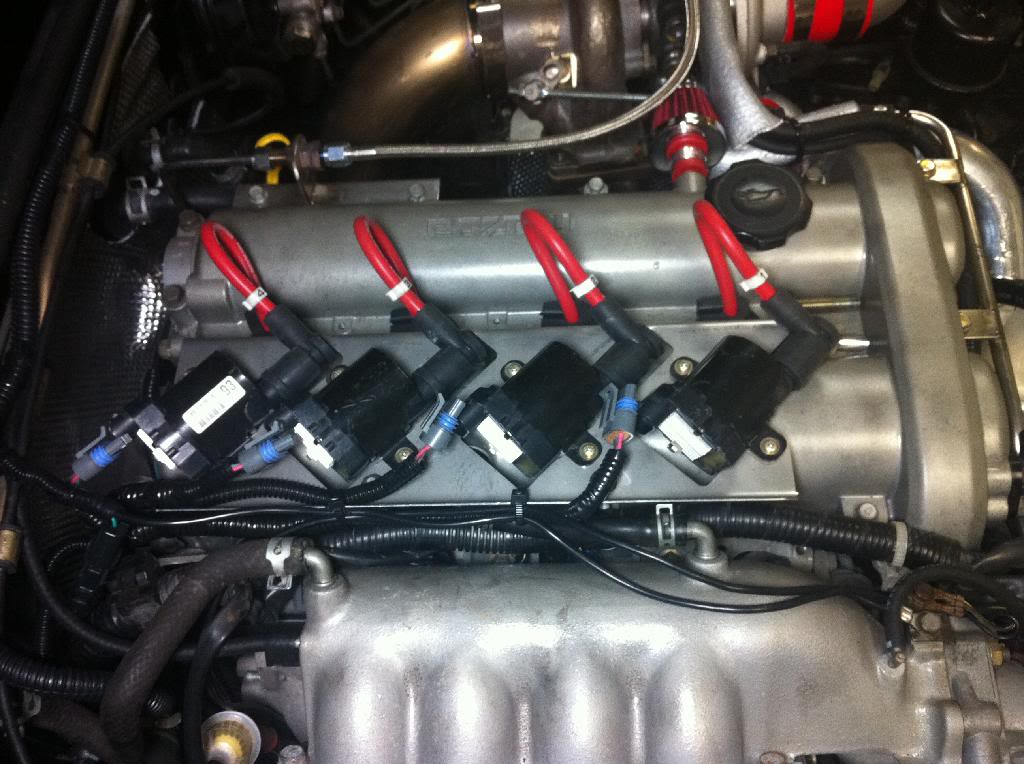

Last edited by HHammerly; 11-23-2015 at 09:45 PM. Reason: adding photo
Reply
0
0
11-23-2015, 09:44 PM
#38
Boost Pope

iTrader: (8)
Join Date: Sep 2005
Location: Chicago. (The less-murder part.)
Posts: 33,022
Total Cats: 6,589
For any given combination of ignition coil and driver, the time required to achieve maximum current differs. Thus, the most optimal method for determining the ideal dwell-time for any given coil is to attach a DC current probe to its primary side and look at it with an oscilloscope.
Here are some scope traces I took years ago of the stock coils on an '02. First, I dwell the coil for about 4.7ms:
(pardon the noise- lazy wiring on my part.)
I don't remember the scale of the probe I was using at the time. Let's arbitrarily say that it's 1V / A.
You can clearly see the coil current start at around 1.5 A and then starts rising more or less linearly. After about 3.1 ms, the coil primary reaches saturation and the current levels off at 2.2A. Dwelling the coil beyond this point produces no further rise in primary current, so in this example I'm just needlessly creating excess heat.
Here, I decrease the dwell time to about 3ms:
This is just about right. The primary cuts off at pretty much the exact point that primary current reaches its maximum. I could have dwelled the coil for another few tenths of a ms just to be safe, but this is in the ballpark.
Reply
0
0
11-23-2015, 10:24 PM
#39
Senior Member
Thread Starter
iTrader: (3)
Join Date: Dec 2007
Location: Brownsburg,IN
Posts: 837
Total Cats: 63
Thanks Joe, i will set the dwell to 3.1 ms and get the car re-tuned, i would have expected that very long dwell timing would retard timing as rpm increases rather than advance it...
I set the dwell to the 5MS time because i found in this in MegaManual.
"The LS1 built in coil igniters (the amplifier that drives the coil's primary current based on the sequencer signal) will follow the sequencer signal pulse width. When the signal from the sequencer is high (3 to 5+ Volts - with very little current from the controller, a few dozen milliAmps), the coil current will be building. When the signal from the sequencer is pulled low (shut off), the coil will spark. The duration of the signal from the sequencer determines the dwell (though the coil igniter limits this to no more than ~8 milliseconds).
As the dwell time increases, the peak coil charge current increases. The coil output current is not as linear. The LS1 coils do not fully saturate until around 8 milliseconds, but the spark energy does not increase much when the dwell exceeds 6 milliseconds. So stick with a 'running' dwell setting near the design value of 5.6 to 5.8 milliseconds. This will keep the coils cooler and extend their life. Note that MegaSquirt-II uses a nominal dwell setting, called the 'maximum dwell', at 12.0 Volts and adjusts this for the continuously measured running voltage (since higher voltages charge the coil more quickly, the dwell is shortened, and conversely, low cranking voltages need extended dwells to properly charge the coil for easy starting).
To get 5.6 milliseconds of running dwell, the nominal dwell parameters should be set to: "
Reply
0
0
11-23-2015, 10:34 PM
#40
Boost Pope
iTrader: (8)
Join Date: Sep 2005
Location: Chicago. (The less-murder part.)
Posts: 33,022
Total Cats: 6,589
I posted the above simply to illustrate a point. I have utterly no idea what the optimal dwell time for your coils. That's why Ben was asking you if you'd scoped them.
It will do neither. (edit: further discoveries a few posts down, because whoever designed your coils is a moron) The ECU is smart enough to calculate dwell based on the predicted end-time to achieve a given timing advance. Long dwell times only become an issue when they are so long that they exceed the engine's cycle time (or 1/2 the cycle time, if batch fire), and that doesn't happen at reasonable RPMs with real-world coils.
I don't think dwell time is the root cause of whatever problem you're having. I'm not 100% certain it isn't but I can't see how it would be.
6-8 ms seems like a really long dwell period to me, but again, you'll only know for sure if you scope them.
In the absence of scope data, I'd tend to trust the manual. Also, ideal dwell time varies with voltage. There's no one single number which is ideal for all cars.
i would have expected that very long dwell timing would retard timing as rpm increases rather than advance it...
I don't think dwell time is the root cause of whatever problem you're having. I'm not 100% certain it isn't but I can't see how it would be.
"The LS1 built in coil igniters (the amplifier that drives the coil's primary current based on the sequencer signal) will follow the sequencer signal pulse width. When the signal from the sequencer is high (3 to 5+ Volts - with very little current from the controller, a few dozen milliAmps), the coil current will be building. When the signal from the sequencer is pulled low (shut off), the coil will spark. The duration of the signal from the sequencer determines the dwell (though the coil igniter limits this to no more than ~8 milliseconds).
As the dwell time increases, the peak coil charge current increases. The coil output current is not as linear. The LS1 coils do not fully saturate until around 8 milliseconds, but the spark energy does not increase much when the dwell exceeds 6 milliseconds. So stick with a 'running' dwell setting near the design value of 5.6 to 5.8 milliseconds. This will keep the coils cooler and extend their life. Note that MegaSquirt-II uses a nominal dwell setting, called the 'maximum dwell', at 12.0 Volts and adjusts this for the continuously measured running voltage (since higher voltages charge the coil more quickly, the dwell is shortened, and conversely, low cranking voltages need extended dwells to properly charge the coil for easy starting).
As the dwell time increases, the peak coil charge current increases. The coil output current is not as linear. The LS1 coils do not fully saturate until around 8 milliseconds, but the spark energy does not increase much when the dwell exceeds 6 milliseconds. So stick with a 'running' dwell setting near the design value of 5.6 to 5.8 milliseconds. This will keep the coils cooler and extend their life. Note that MegaSquirt-II uses a nominal dwell setting, called the 'maximum dwell', at 12.0 Volts and adjusts this for the continuously measured running voltage (since higher voltages charge the coil more quickly, the dwell is shortened, and conversely, low cranking voltages need extended dwells to properly charge the coil for easy starting).
In the absence of scope data, I'd tend to trust the manual. Also, ideal dwell time varies with voltage. There's no one single number which is ideal for all cars.
Last edited by Joe Perez; 11-24-2015 at 11:40 AM.
Reply
0
0


