Few more diypnp build questions
 07-01-2011, 01:33 PM
#1
Senior Member

Thread Starter
iTrader: (6)

Join Date: May 2009
Location: San Francisco
Posts: 983
Total Cats: 23
I've gotten through a lot of the build, now i have some questions.
1. I've gotten to step 7 here: U5, Q7, Q11, Q12, and Q17 all install on the underside of the board. Put a dab of heat sink compound on the metalized area of the board and bolt them into place with the provided hardware before soldering them down.
For Q17, i don't know the order of how the pieces are bolted down. I am guessing that the plastic piece goes between the bottom of q17 and the heat sink on the board, but does heat sink compound go on both sides of the plastic? And does it matter which side the plastic washer thing is on? Heres a picture of all the pieces:
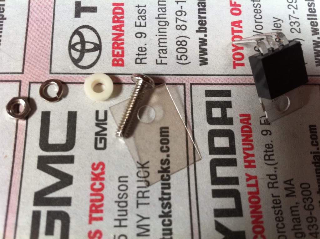
2. Also, the rest of the pieces in that step don't have bolts in the package to bolt them down or any of the plastic pieces. Do they need plastic pieces, and which screws do i use to bolt down? the 12 4-40 machine screws? If someone has a close up pic of this step, that would be awesome.
1. I've gotten to step 7 here: U5, Q7, Q11, Q12, and Q17 all install on the underside of the board. Put a dab of heat sink compound on the metalized area of the board and bolt them into place with the provided hardware before soldering them down.
For Q17, i don't know the order of how the pieces are bolted down. I am guessing that the plastic piece goes between the bottom of q17 and the heat sink on the board, but does heat sink compound go on both sides of the plastic? And does it matter which side the plastic washer thing is on? Heres a picture of all the pieces:
2. Also, the rest of the pieces in that step don't have bolts in the package to bolt them down or any of the plastic pieces. Do they need plastic pieces, and which screws do i use to bolt down? the 12 4-40 machine screws? If someone has a close up pic of this step, that would be awesome.

Reply
 0
0

0
07-01-2011, 01:43 PM
#2
Senior Member
Thread Starter
iTrader: (6)
Join Date: May 2009
Location: San Francisco
Posts: 983
Total Cats: 23
nvm think i found the answer in this thread:
https://www.miataturbo.net/showthrea...t=57250&page=2
mica is just a precation for that one, rest use the 4-40 screws and washers
https://www.miataturbo.net/showthrea...t=57250&page=2
mica is just a precation for that one, rest use the 4-40 screws and washers
Reply
0
0
07-01-2011, 01:46 PM
#3
Boost Czar

iTrader: (62)
Join Date: May 2005
Location: Chantilly, VA
Posts: 79,493
Total Cats: 4,080
yep. I've had the high side driver put 5v through the ground without using the mica insulator once. there's a 5v sourec that's very close to the heatsink pad and you can position the FET in just a way to make contact with it. So it goes between the board and the FET to prevent that from happening. the plastic donut prevents the metal screw from contacting the metal tab.
Reply
0
0
07-01-2011, 01:52 PM
#4
Supporting Vendor

iTrader: (33)
Join Date: Jul 2006
Location: atlanta-ish
Posts: 12,659
Total Cats: 134
Mica is only needed for the highside driver, Q17. It's just a precaution as there is a VIA near Q17 that if you try hard enough can be shorted to Q17. The order of assembly, as viewed from the top down...
nut
lockwasher
mainboard
mica
transistor
plastic washer
screw
Apply a very small amount of the included thermal paste on each side of the mica.
nut
lockwasher
mainboard
mica
transistor
plastic washer
screw
Apply a very small amount of the included thermal paste on each side of the mica.

Reply
0
0
07-01-2011, 03:53 PM
#5
Senior Member
Thread Starter
iTrader: (6)
Join Date: May 2009
Location: San Francisco
Posts: 983
Total Cats: 23
Now i'm trying to figure out what to do/not do to setup sequential fuel and spark. I don't have the seqential fuel board yet (won't have until july 12) so i don't want to do anything that will make installing that more difficult.
Also, i'm reading this page at the very bottom looking at the different ignition wiring options. http://www.diyautotune.com/diypnp/do..._assembly.html
do i need to have cops to wire and run sequential, or will it run sequential on my stock ignition setup. If i need cops, it seems easy to just wire the left two for wasted spark right now and add the other two later when i add COPS.
Reply
0
0
07-01-2011, 06:35 PM
#6
Senior Member
Thread Starter
iTrader: (6)
Join Date: May 2009
Location: San Francisco
Posts: 983
Total Cats: 23
Bleh, i'm done for today. I dont want to rush anything and screw anything up. Im done with everything up to step 15 on the main assembly sheet:http://www.diyautotune.com/diypnp/do..._assembly.html
So now i need to attach the adapter board and connect all the pull ups from this thing:http://www.diyautotune.com/diypnp/ap...5-18bp-mt.html
What do i need to do/not do on this list to run sequential fuel? I'm kinda lost at this point. It says pull ups, so do i use the extra "pull up" resistors i have, or just use wire to make all these connections.
I'm basically looking for some pointers on where to go from this point. Should i wait until i have the sequential module to put that on first, or can i keep going. Not in a huge hurry, but any help is gladly appreciated.
Reply
0
0
07-04-2011, 01:09 PM
#7
Elite Member
iTrader: (4)
Join Date: Aug 2009
Location: Redwood City, CA
Posts: 1,784
Total Cats: 42
You'd have to go to COPs to run sequential spark, I'm pretty sure all year NA's run 2 coils in waste spark config? Unless you mean wire the 2 coils in sequential, I don't remember if each coil has a single ground wire.
Reply
0
0
08-24-2011, 02:34 AM
#8
Senior Member
Thread Starter
iTrader: (6)
Join Date: May 2009
Location: San Francisco
Posts: 983
Total Cats: 23
Guys i need some help finishing this up.
I have three main areas of concern:
Jumpers,
Sequential Injection Setup,
wbo2
Firstly, Jumper connections.
Do I follow this page exactly? Or are there some differences because I am going to run seq inj and a wbo2?
Also, do i solder to the upper or lower section of solder holes because there are two of each designation (4N, 4O, 4P, etc.)
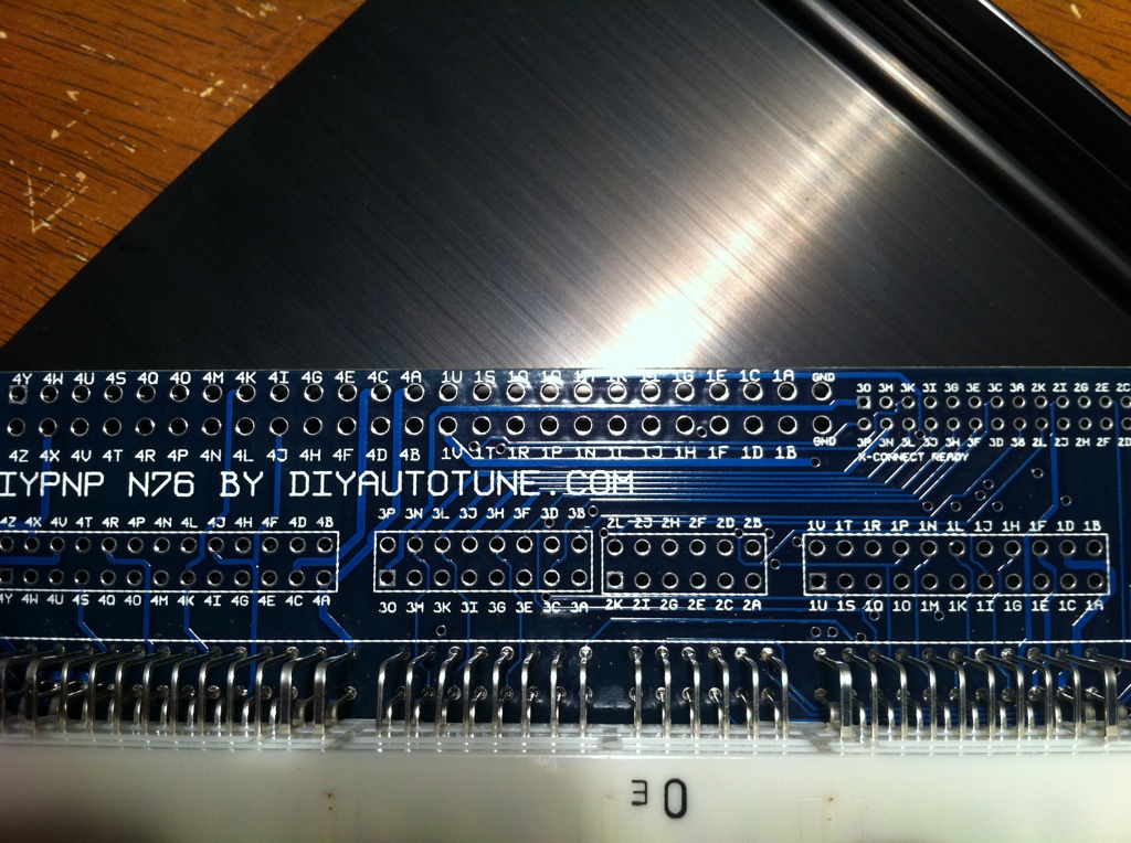
Next, sequential injection. There are 4 holes on the main board for inj 1 and inj 2, and one hole for inj 3 and inj 4 on the seq mod board. Which inj1 and inj2 holes do i use, and what pins do i use for all 4 injectors on the adapter board? Im referring to the main board as the big one and adapter as the one in the picture above.
Lastly, wb02 hookup. Do i connect the o2 to 4N? Or do i need to connect a wire to my db15 connector to wire in the input from my uego?
Hopefully someone can help me out, thanks a ton guys.
I have three main areas of concern:
Jumpers,
Sequential Injection Setup,
wbo2
Firstly, Jumper connections.
Do I follow this page exactly? Or are there some differences because I am going to run seq inj and a wbo2?
Also, do i solder to the upper or lower section of solder holes because there are two of each designation (4N, 4O, 4P, etc.)
Next, sequential injection. There are 4 holes on the main board for inj 1 and inj 2, and one hole for inj 3 and inj 4 on the seq mod board. Which inj1 and inj2 holes do i use, and what pins do i use for all 4 injectors on the adapter board? Im referring to the main board as the big one and adapter as the one in the picture above.
Lastly, wb02 hookup. Do i connect the o2 to 4N? Or do i need to connect a wire to my db15 connector to wire in the input from my uego?
Hopefully someone can help me out, thanks a ton guys.
Reply
0
0
08-24-2011, 02:47 AM
#9
Elite Member
iTrader: (10)
Join Date: Jun 2006
Location: Athens, Greece
Posts: 5,977
Total Cats: 356
Next, sequential injection. There are 4 holes on the main board for inj 1 and inj 2, and one hole for inj 3 and inj 4 on the seq mod board. Which inj1 and inj2 holes do i use, and what pins do i use for all 4 injectors on the adapter board? Im referring to the main board as the big one and adapter as the one in the picture above.
Inj1 is cylinder 1, inj2 is cylinder 3, "3" is cylinder 4 and "4" is cylinder 2. Map them according to the instructions found in the DIYPNP manual.
To the DB15.
Reply
0
0
08-24-2011, 03:06 AM
#10
Senior Member
Thread Starter
iTrader: (6)
Join Date: May 2009
Location: San Francisco
Posts: 983
Total Cats: 23
Reverant thank you you're a god, but i cant seem to find the "DIYPNP manual which tells me where to connect each of the four injectors. I'm guessing it is between 4Y, 4Z, 4U, and 4V though because in wasted spark mode those are the four used.
any tips on where i need to look for the manual?
any tips on where i need to look for the manual?
Reply
0
0
08-25-2011, 02:55 PM
#15
Senior Member
Thread Starter
iTrader: (6)
Join Date: May 2009
Location: San Francisco
Posts: 983
Total Cats: 23
Last two questions before I test it out with the power supply!
How do i wire the OPTO GND and BL/TH off like it says on the jumper manual?
Pictures of the OPTO GND and BL/TH:
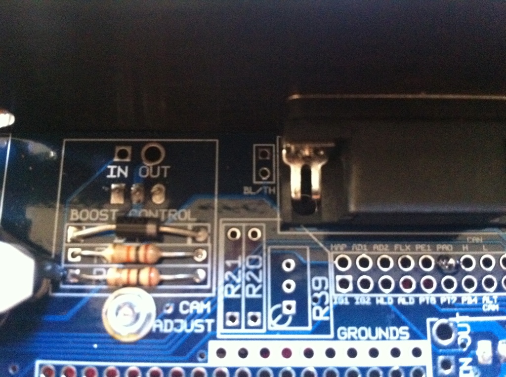
How do i wire the OPTO GND and BL/TH off like it says on the jumper manual?
Pictures of the OPTO GND and BL/TH:
Reply
0
0

Thread
Thread Starter
Forum
Replies
Last Post
Mikel
MEGAsquirt
4
09-28-2015 04:46 PM


