Franks plug and play MS3-Extra on 92 NA6CE
 11-23-2013, 06:50 PM
#1
Junior Member
Thread Starter

Join Date: Oct 2013
Location: Yokohama
Posts: 51
Total Cats: 2
I'm now following Frank's instructions on how to build the MS3-MS3X PnP for 90-94.
So far the instructions seem pretty straight forward and all tests with the voltmeter and according to mega manual are fine (I used a 9v battery to test). Would these tests fail if I had overheated/damaged a component?
I also installed the LEDs and DB9 socket. Please let me know if anything doesn't look right.
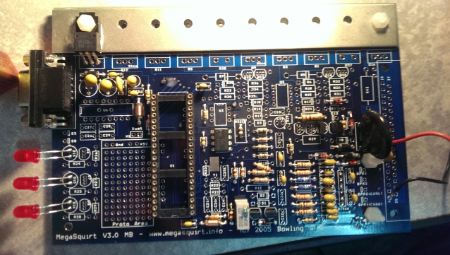
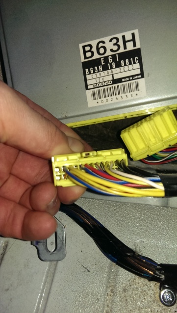
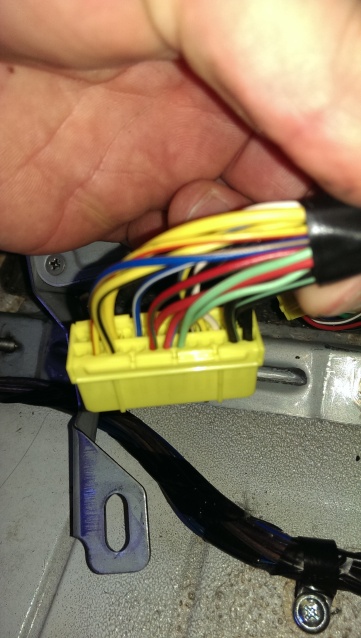
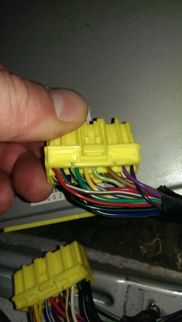
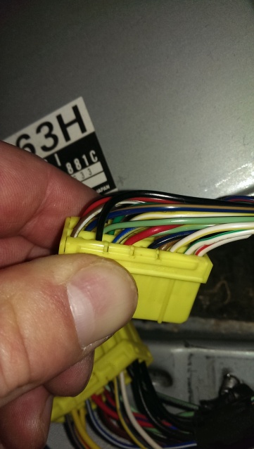
Does anyone know of any difference between the JDM NA6CE and ADM Miata ECU pinouts that I will need to adjust for? Here are some pics:
Thanks!
So far the instructions seem pretty straight forward and all tests with the voltmeter and according to mega manual are fine (I used a 9v battery to test). Would these tests fail if I had overheated/damaged a component?
I also installed the LEDs and DB9 socket. Please let me know if anything doesn't look right.
Does anyone know of any difference between the JDM NA6CE and ADM Miata ECU pinouts that I will need to adjust for? Here are some pics:
Thanks!

Reply
 0
0

0
11-24-2013, 01:15 PM
#2
Senior Member

Join Date: Nov 2007
Location: Belgium
Posts: 999
Total Cats: 73
The test wouldn't fail, but it's unlikely you overheated something.
The wiring on your JDM is identical to the wiring diagram on my site. You have NO sequential fuel so don't use the sequential wiring diagram though.
If you don't want to cut up the wiring on your AFM connector, I suggest you use fuel pump method 1. It's a bit harder because you need to stick your head under the dash, but at least the wiring under the hood stays intact.
Same thing for the air temp sensor. Instead of bringing the air temp signal in through the black and red/green wires of the AFM connector, it's much simpeler to use the wire for the power steering pump instead. That wire is not used, regardless if you have power steering or not.
Find the blue/yellow wire in the front of your engine. If you have PS, it goes to the PS pump. If you don't have PS, it's tied in a loop near the thermostat house.
Connect that wire to one of the two air temp sensor wires (it doesn't matter which) and ground the other air temp sensor wire to the throttle body.
Your air temp signal now comes in on pin 1P (blue/yellow) instead of pin 2P (red/green) so change your wiring inside the MS3 accordingly. IOW, inside the MS3 case, you need to connect mainbord pin 20 to 1P instead of to 2P.
Looks like you've got everything covered except for the DB9 and the LEDs.
If you want to use these, you need to install everything with * and ** in my instructions here: http://westfieldmx5.devocht.com/mega...ms3/99-05-ms3/
Basically, install all components on the left side of the 40 pin connector in your first picture.
It seems I forgot to add that option in the 90-97 instructions.
Last edited by WestfieldMX5; 11-24-2013 at 03:46 PM.
Reply
0
0
11-24-2013, 11:43 PM
#3
Junior Member
Thread Starter
Join Date: Oct 2013
Location: Yokohama
Posts: 51
Total Cats: 2
Advice directly from the man who wrote the guide! Fantastic! Thanks for your help.
I'll do just that with the air temperature sensor and fuel pump.
I read the 99 guide and agree. I'm not going to use the db9 or see the leds so won't get them working but I'll leave them in to plug holes in the case!
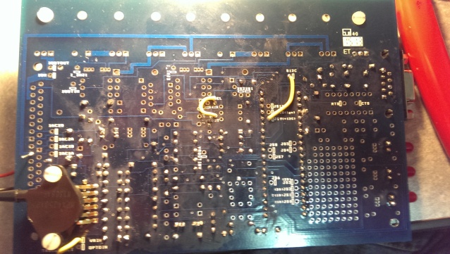
As for the flyback diodes, I've followed your instructions and installed them between 12v and idle; 12v and ac out; and 12v and fan out. The pinout diagram shows 12v/diodes joining different wires though (boost, idle and fuel pump). I'm assuming that this is my misunderstanding but hoping you can confirm this.
I've got the VTPS at home and an MTX-L on its way. Hoping to get the car running next weekend.
Thanks again!
I'll do just that with the air temperature sensor and fuel pump.
I read the 99 guide and agree. I'm not going to use the db9 or see the leds so won't get them working but I'll leave them in to plug holes in the case!
As for the flyback diodes, I've followed your instructions and installed them between 12v and idle; 12v and ac out; and 12v and fan out. The pinout diagram shows 12v/diodes joining different wires though (boost, idle and fuel pump). I'm assuming that this is my misunderstanding but hoping you can confirm this.
I've got the VTPS at home and an MTX-L on its way. Hoping to get the car running next weekend.
Thanks again!
Reply
0
0
 11-27-2013, 04:47 AM
#6
Junior Member
Thread Starter
Join Date: Oct 2013
Location: Yokohama
Posts: 51
Total Cats: 2
I'm low on space inside the case so I'll install the other flyback diodes outside.
I'm now doing Part 4: Final adjustments of the VR circuits and I'm not seeing a voltage change on the upper leg of R54 when I turn R56. It stays around 3.5v. I am using a 9v supply though and no MS3 CPU card or MS3X.
Should I have it all installed now and should I try it on 12v.
I'm now doing Part 4: Final adjustments of the VR circuits and I'm not seeing a voltage change on the upper leg of R54 when I turn R56. It stays around 3.5v. I am using a 9v supply though and no MS3 CPU card or MS3X.
Should I have it all installed now and should I try it on 12v.
Reply
0
0
11-27-2013, 11:35 AM
#7
Senior Member
Join Date: Nov 2007
Location: Belgium
Posts: 999
Total Cats: 73
3.5V is right at the edge so it might work as is but it's not normal. 9V should be plenty because that circuit is fed from the 5V supply.
You sure you didn't short the legs of Q23 ?
http://msextra.com/doc/general/pix/v3pcb_3.gif
You sure you didn't short the legs of Q23 ?
http://msextra.com/doc/general/pix/v3pcb_3.gif
Reply
0
0
11-28-2013, 07:45 AM
#8
Junior Member
Thread Starter
Join Date: Oct 2013
Location: Yokohama
Posts: 51
Total Cats: 2
I have checked the legs of Q23 and they aren't shorted but this is the component I was worried that I had over heated. I did make a solder bridge when I first fitted it and in removing/repairing it the transistor got very hot. Q23 and maybe Q22 are broken.
With an accurate voltmeter I measure 4.84v on the top leg of R34 despite changing R56. Could an overheated Q23 be the cause? Could R56 be bad?
Just to confirm - I'm running these tests without the CPU in place.
Thanks for the help!!
With an accurate voltmeter I measure 4.84v on the top leg of R34 despite changing R56. Could an overheated Q23 be the cause? Could R56 be bad?
Just to confirm - I'm running these tests without the CPU in place.
Thanks for the help!!
Reply
0
0
08-07-2014, 05:45 PM
#11
SADFab Destructive Testing Engineer


iTrader: (5)
Join Date: Apr 2014
Location: Beaverton, USA
Posts: 18,642
Total Cats: 1,866
Kind of pulling this up from the dead but I have a question about the flyback diodes. I've been reading about them in a couple threads and you talk about the for the NB plug and play build but not in the 1.6 NA build on your site. Are the flyback diodes necessary for that build and where is the best place to wire them?
Reply
0
0

Thread
Thread Starter
Forum
Replies
Last Post
StratoBlue1109
Miata parts for sale/trade
21
09-30-2018 01:09 PM


