MS3, MS3x, 1ZZ COP, Sequential Fuel and Spark
 04-18-2012, 08:58 AM
#1
Newb
Thread Starter

Join Date: Apr 2010
Posts: 19
Total Cats: 0
Hi Guys,
I'm fairly new on this forum, but not to Miatas. Over the last 2 years I have been building up my project car (dubbed Project:Bankruptcy) and have been keeping a build thread over at MX5Nutz.com if you want to see her this is her thread.
I am currently swapping my ECU from TEC2 to MS3.
I have been doing a lot of reading, and think i am heading in the right direction, but time is getting shorter before she needs to be on the road, and i am hoping for some confirmation that i am heading in the right direction.
Details.
Engine is a mk1 1.8
Engine loom is all fresh using the looms supplied by DIYautotune (the previous TEC install and wire tuck meant there was none of the original harness in place)
I am aiming to use:-
MS3 and MS3x to run COPs sequentially with sequential fuel.
Crank trigger is Hall sensor (again from DIYAutotune) with 36-1 toothed wheel
Cam trigger is a modified 97 CAS (as here, not optical) i have modified it to remove the largerof the 2 "tabs" on the inner cam ring.
COPS is 1zz coils, as here
Injectors are EV14 high impedance 650cc
also running with FMIC, TD04 turbo, electronic boost control.
I believe I have worked out quite a bit of the details, but i am struggling with some too :( and would like some confirmations before plugging everything in and making a costly mistake.
CAS wiring:-
I believe i need only to connect a fused 12v, and ground to the CAS -pin to any earth on the main MS3 v3 board (such as pin19)
then connect the CAM signal wire from the MS3x board (pin 32)
is this correct?
Injector Wiring:-
fused +12 to one side of the injectors, then connect the MS3x to the other pin,
INJ A to Cylinder 1
INJ B to Cylinder 3
INJ C to Cylinder 4
INJ D to Cylinder 2
COPS, Similar to the Injector wiring? ie supply each COP with fused 12v, 0v earth on head, tie all tach pins together, and the SPK pins from the MS3x to the relevant COP logic pin? no other electrics needed
Spark A to Cylinder 1
Spark B to Cylinder 3
Spark C to Cylinder 4
Spark D to Cylinder 2
adjust dwell settings to 3.5ms cranking, 2.5ms at 12v
as described for an even fire engine at this page on MSExtra.com no other electrics required?
sorry for all the questions :( but hopefully i have reduced them to yes/no answers. I will probably have a few more in the next few days with respect to the settings in tuner studio, I have had it running on my jimstim so hopefully i won't have many.
Thanks in advance for any help you can give me
Matt
Gratuitous engine bay shot as it stands at the moment...
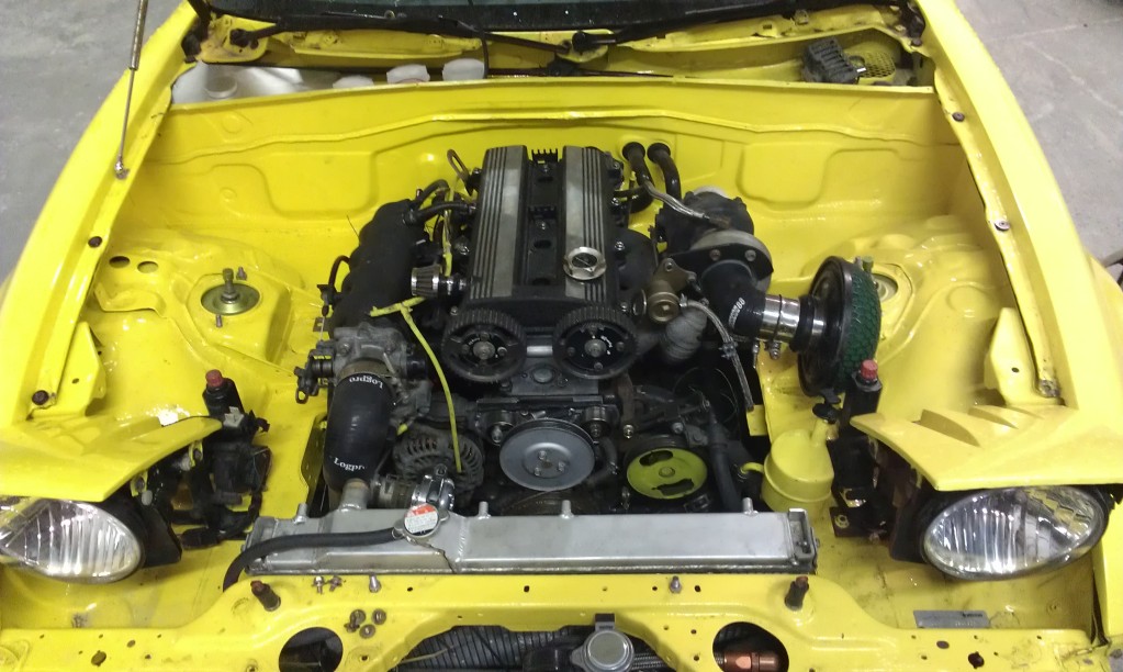
Last edited by Yetidragon; 04-18-2012 at 09:30 AM.

Reply
 0
0

0
04-18-2012, 09:30 AM
#4
mkturbo.com


iTrader: (24)
Join Date: May 2006
Location: Charleston SC
Posts: 15,176
Total Cats: 1,680
Everything looked right in your first post. Also we do not mind questions at all as long as you have shown that you have searched and are not asking completely stupid question. Your first post showed that you are reasonably smart are on the right track, so ask away.
Reply
0
0
 04-23-2012, 05:57 AM
#8
Elite Member
iTrader: (1)

Join Date: Jun 2006
Location: Warrington/Birmingham
Posts: 2,642
Total Cats: 42
I ask as when temps drop below 0degC my car does not start, diagnosed to be no spark, as soon as temps increase spark re-appears. Just wondering is the cold reduces the batt voltage.
Yeti, sorry for the segway.
Reply
0
0
05-03-2012, 08:04 PM
#10
Newb
Thread Starter
Join Date: Apr 2010
Posts: 19
Total Cats: 0
just a quick update.
So i went ahead and wired it all up.
I downloaded Braineacks basemap and adjusted for my config.
bangs happened...
checked config, realised i missed some DOH check twice in future!
she started, but very unwillingly, idled very lumpy, rev up was very hesitant, frequent cut outs.
Checked phasing of signal on cam after a friend suggested it.
Realised cam sig was 180 deg out, a bit of adjustment later and she is starting a lot better, still not every time, but 90% DOH check twice in future! (i will learn that!)
when first started, if you try to put any throttle at all, she cuts out, but after 30secs or so she gradually improves. she is now idling and reving up reasonably well ( for a given value of reasonable)
I will finish off my coolant system tomorrow so i can run her for longer than a few seconds and see how she behaves (only had her on for extremely short periods for this very early testing)
all in all i feel it has gone very well so far and i am looking forward to improving on it over the next few days. I have a show next Saturday, so i'm working to a bit of a tight deadline, especially with a lot of brake work and wiring still to go, but with the help of my friends ( I have got some very great mates) I am hoping to get he into a good enough state to make the 300mile round trip next weekend.
No doubt i will be coming looking for some advise over the next few days, as i am very new to this (eager to learn though)
Thank you very much for all the help and comments so far. I'll try and my adjusted version of Braineacks basemap in a sec. Hopefully it can help someone if they are building a similar set up as mine. I havn't made any adjustment to any of the maps from Braineacks original, all adjustment so far has been for the different crank / cam triggers, larger injectors and different fan control. (VVT pin)
If anyone has any comments on it then I welcome all input i will post back as i continue over the next couple of days
So i went ahead and wired it all up.
I downloaded Braineacks basemap and adjusted for my config.
bangs happened...
checked config, realised i missed some DOH check twice in future!
she started, but very unwillingly, idled very lumpy, rev up was very hesitant, frequent cut outs.
Checked phasing of signal on cam after a friend suggested it.
Realised cam sig was 180 deg out, a bit of adjustment later and she is starting a lot better, still not every time, but 90% DOH check twice in future! (i will learn that!)
when first started, if you try to put any throttle at all, she cuts out, but after 30secs or so she gradually improves. she is now idling and reving up reasonably well ( for a given value of reasonable)
I will finish off my coolant system tomorrow so i can run her for longer than a few seconds and see how she behaves (only had her on for extremely short periods for this very early testing)
all in all i feel it has gone very well so far
and i am looking forward to improving on it over the next few days. I have a show next Saturday, so i'm working to a bit of a tight deadline, especially with a lot of brake work and wiring still to go, but with the help of my friends ( I have got some very great mates) I am hoping to get he into a good enough state to make the 300mile round trip next weekend.No doubt i will be coming looking for some advise over the next few days, as i am very new to this (eager to learn though)
Thank you very much for all the help and comments so far. I'll try and my adjusted version of Braineacks basemap in a sec. Hopefully it can help someone if they are building a similar set up as mine. I havn't made any adjustment to any of the maps from Braineacks original, all adjustment so far has been for the different crank / cam triggers, larger injectors and different fan control. (VVT pin)
If anyone has any comments on it then I welcome all input
i will post back as i continue over the next couple of days
Last edited by Yetidragon; 05-03-2012 at 09:08 PM.
Reply
0
0
05-03-2012, 08:11 PM
#11
Newb
Thread Starter
Join Date: Apr 2010
Posts: 19
Total Cats: 0
overview of setup:-
1.8
MS3, MS3x, 1ZZ COP, Sequential Fuel and Spark
36-1 crank wheel
Modified early model CAS (large lobe cut off cam trigger, then small lobe rotated through 180deg)
EV14 650ccInjectors
Elec boost control
Intercooler
LC-1 wideband
using diyautotune loom, not mx5 wiring.
VVt line used for Fan control
Attached, Braineacks Basemap, modified with settings for above triggers and injectors
Last edited by Yetidragon; 05-03-2012 at 09:06 PM.
Reply
0
0
 05-04-2012, 07:59 AM
#13
Newb
Thread Starter
Join Date: Apr 2010
Posts: 19
Total Cats: 0
If you are doing sequential fuel and spark then the ECU needs to know which TDC you are at (as there are 2 TDCs for each cycle of the engine)
so you use the cam signal to tell the ecu when the TDC on the compression stroke of cylinder 1 is about to happen, well thats how i read it anyway

Reply
0
0
05-04-2012, 08:01 AM
#14
Newb
Thread Starter
Join Date: Apr 2010
Posts: 19
Total Cats: 0
Explained a little on how to set it up here http://www.msextra.com/doc/ms3/trigg...html#misscrank in the section headed "Missing tooth crank wheel and single tooth cam wheel"
If you need some guidance on the CAS mod then gimmie a shout. richyvrlimited helped me out with some notes, and i took some pics while doing mine to put up a how to on my website as I had a devil of a time finding details.
If you need some guidance on the CAS mod then gimmie a shout. richyvrlimited helped me out with some notes, and i took some pics while doing mine to put up a how to on my website as I had a devil of a time finding details.
Reply
0
0
05-04-2012, 08:41 AM
#15
Makes sense for cam sensor to tell MS which TDC it is.
yeas I would be interested in seeing waht you did to rotate the phase of cam signal 180 degrees. No setting in MS would allow this in software?
I guess one could also change the ignition and injector wires for A to D and from B to C to change the phase.
hrk
yeas I would be interested in seeing waht you did to rotate the phase of cam signal 180 degrees. No setting in MS would allow this in software?
I guess one could also change the ignition and injector wires for A to D and from B to C to change the phase.
hrk
Reply
0
0
05-04-2012, 08:49 AM
#16
Supporting Vendor

iTrader: (33)
Join Date: Jul 2006
Location: atlanta-ish
Posts: 12,659
Total Cats: 134
Cam signal is required to relate engine phase as the full engine cycle is 720� (2 revolutions) of crank revolution. This is required only for sequential fuel and/or ignition.
Reply
0
0
05-04-2012, 08:53 AM
#17
Newb
Thread Starter
Join Date: Apr 2010
Posts: 19
Total Cats: 0
If you have an early one like this http://www.rivercityroad.com/garage/cas.htm
then you need only use the SGC wire. this links to teh sensor on inner ring of teeth.
I trimmed off the larger of the 2 inner lobes, as i understood the shorter the signal the better (to prevent over lap of signal with Crank)
this unfortunately left the signal i had on the wrong phase of the engine.
the inner ring is spun by the outer ring, with just a small raised dimple engaging from the inner, into a hole on the outer, I drilled another hole 180deg around the outer and used that to engage the 2 rings instead.
I guess removing the smaler of the 2 lobes would have had me on the correct phase any way, then i could have narrowed the lobe down if i was getting over lap.
Simples when you have it apart in front of you
Reply
0
0
05-08-2012, 02:52 AM
#20
Newb
Thread Starter
Join Date: Apr 2010
Posts: 19
Total Cats: 0
Well the weekend saw the a lot of progress, and a few set backs.
The actuator for my waste gate appears to be broken.
And my wideband appears to be having some problems. In tuner studio it just shows 7.5 or 10.10 on the number in the centre of the ego gauge (volts?) , and on the gauge, it always just reads at the extremities of the gauge. On the physical gauge it only reads the extremities too.
It is an lc-1 and I know most issues with these are caused by wiring or can be solved with a free air calibration / reset. I currently don't have a laptop with a serial port to connect to it, but the calibration led isn't flashing any error code. I have followed manual details for reset and disconnected the sensor, turned on for a few seconds, then turned on for 2mins to allow it to reset and free air calibrate.
I know most common issue appear to be caused by the ground connection, so would like to confirm what I have done is correct as some of my source reading appears conflicting.
At present, all but 2 of the earth pins on the megasquirt and MS3x go to the back of the head. 1 of the remaining is used to ground the sensors around the engine. (as described in the DIYautotune loom instructions) the 1 remaining pin goes to the same earthpoint behind the dash as the lc-1.
Should they be earthed to the body? Or should the earth pin from the ms be providing the ground for The lc-1 alone?
The sensor has been bench tested and shown to be working fine on a friends mc-1
I'm currently seeking a laptop with serial port to connect to the lc-1, but would appreciate some feedback on the above wiring.
Thanks in advance.
Reply
0
0


