Help with Braineack built MS3 - fuel pump circuit
 05-12-2016, 02:37 PM
#1
Cpt. Slow

Thread Starter
iTrader: (25)
Join Date: Oct 2005
Location: Oregon City, OR
Posts: 14,179
Total Cats: 1,130
I'm working on a MSM with no fuel pump. I've tested the FP relay, and it's functional with continuity to the ECU plug. When grounded there, the relay is working and the fuel pump is turning on.
Continuity is also good on the MS harness from the ECU plug through the DB37 plug.
What should I be looking for on the MS3 board itself? I've also tested that pin and it is not grounding when tested in test mode. It appears to go to D4? Does this fry like the older MS1/2s? Is there a fuse that needs to be removed? Sorry for lack of knowledge on this project, no documentation was given to me after the owner gave up trying to get it running.

Reply
 0
0

0
05-12-2016, 02:54 PM
#2
Boost Czar

iTrader: (62)
Join Date: May 2005
Location: Chantilly, VA
Posts: 79,493
Total Cats: 4,080
who's MS is this?
I ask about who's unit it is, because if it was built for a regular NB2 and not MSM specifically, then the FP won't run (along with other things). But it sounds like it's getting 12v...
Can you confirm what pin the purple fuel pump relay wire is populated on the ECU connector? First thing "mechanical" I'd want to double check. It should be at 2M between 12v and Injector C.
Last edited by Braineack; 05-12-2016 at 03:06 PM.
Reply
0
0
05-12-2016, 03:26 PM
#6
Boost Czar
iTrader: (62)
Join Date: May 2005
Location: Chantilly, VA
Posts: 79,493
Total Cats: 4,080
I THINK it was this one: Redirecting
I remember GTred asking me for info getting setup a while back, but havent heard from him in months.
harness should be built to this:

I remember GTred asking me for info getting setup a while back, but havent heard from him in months.
harness should be built to this:
Reply
0
0
 05-12-2016, 10:26 PM
#9
Cpt. Slow
Thread Starter
iTrader: (25)
Join Date: Oct 2005
Location: Oregon City, OR
Posts: 14,179
Total Cats: 1,130
Yeah I appreciate the willingness the lend a hand Aidan. Once the circuit was tested all the way to the DB37 cable, it's outside of my knowledge base. Test mode did indeed provide neither fuel pump operation and/or continuity to ground.
Reply
0
0
05-13-2016, 06:49 AM
#10
Boost Czar
iTrader: (62)
Join Date: May 2005
Location: Chantilly, VA
Posts: 79,493
Total Cats: 4,080
I'd say just send the unit back to me and I'll figure it out and get it back, but I leave for a two-week vacation on the 21st--unsure if we can make that happen in time.
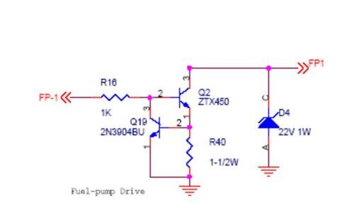
Confirm I didn't put the fuel pump output wire on the wrong ecu connector pin, then we can open the case and see if maybe there's something obvious on the circuit itself, like bridge leads on the Q2 and Q24, or D4 backwards, or R16/R40 missing, or something.
There's a very subtle difference between how a normal 01-05 gets power and how an MSM does as well, so we should also confirm this unit/harness was built for an MSM.
In the meantime if you really just wanted to get it up and running, you can still jump f/p in the diagnostics box.
Reply
0
0
05-13-2016, 10:40 AM
#11
Cpt. Slow
Thread Starter
iTrader: (25)
Join Date: Oct 2005
Location: Oregon City, OR
Posts: 14,179
Total Cats: 1,130
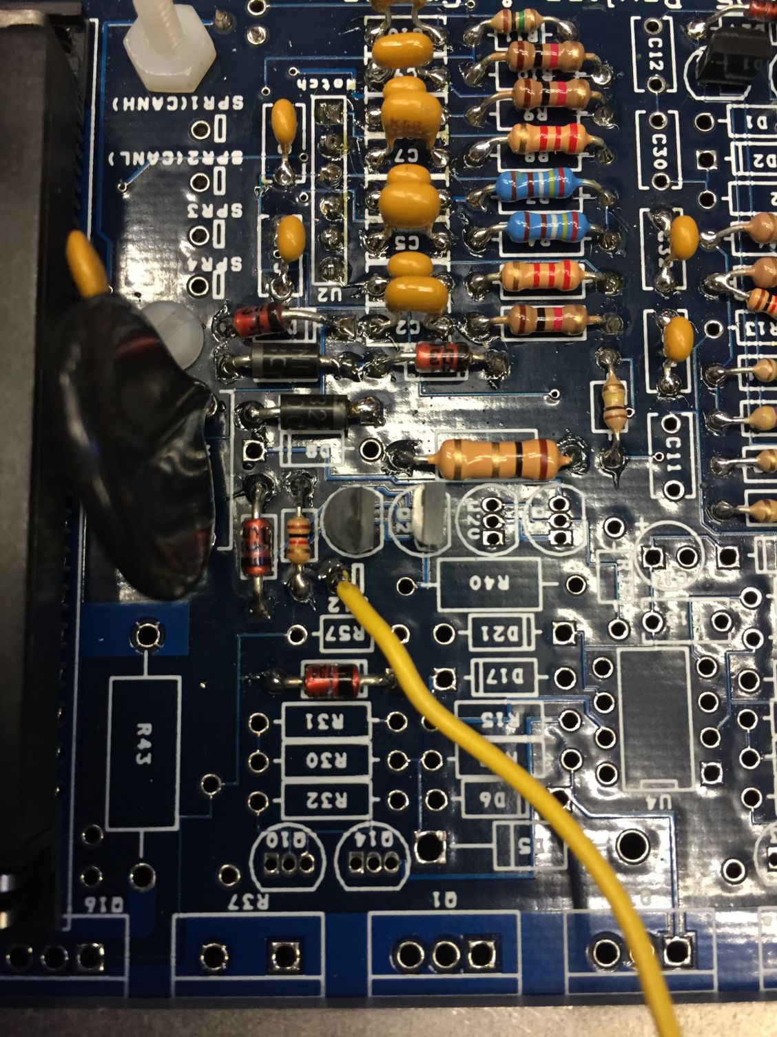
Fuel pump is wired to pin 37 of the lower (main board) connector. It's the single track on the top right of the pins shown on the bottom of the board below. It then jumps over the track directly to the left, and it's other pin is right below where it says "IAC2A". That pin has continuity to the black (ground) wire in the same DB37 cable.

And the top of the board for reference:
I know that injF (G?) is on at -100 coolant temp, I think that's the "subtle difference" you're referring to.
And the top of the board for reference:
I know that injF (G?) is on at -100 coolant temp, I think that's the "subtle difference" you're referring to.
Reply
0
0
05-14-2016, 12:34 PM
#15
Boost Czar
iTrader: (62)
Join Date: May 2005
Location: Chantilly, VA
Posts: 79,493
Total Cats: 4,080
correct. the big fat 1ohm resistor needs to move from R39 to R40.
R39 is the unused idle mainboard controller circuit.
without R40 connecting to ground, the transistors on the fuel pump circuit have nothing to send to the relay. :(
feel free to:

R39 is the unused idle mainboard controller circuit.
without R40 connecting to ground, the transistors on the fuel pump circuit have nothing to send to the relay. :(
feel free to:
Reply
0
0
 05-18-2016, 12:54 PM
#18
Junior Member

Join Date: Apr 2011
Location: Oregon
Posts: 301
Total Cats: 4
It sounds like you have already got this figured out, but here is a link to the classified ad that I purchased this thru: https://www.miataturbo.net/miata-par...s3x-msm-85646/
Thank you all for the assistance.
Thank you all for the assistance.
Reply
0
0
05-18-2016, 06:17 PM
#20
SADFab Destructive Testing Engineer

iTrader: (5)
Join Date: Apr 2014
Location: Beaverton, USA
Posts: 18,642
Total Cats: 1,866
Ben,
what is the bias resistor value?
*EDIT: Called DIY and spoke w/ Matt, who pointed me to megasquirtpnp.com, I had no idea about that page.
On it I found the values, and after using the "GM" drop down which gives you a bias resistor value of 249something (I forget the specific number) populated the values in, seems to be working now
In case anyone needs them:
temp in F-ohms
8-199000
72-35600
180-3800
Reply
0
0


