Help! Car won't start 100 miles from home.
 04-01-2011, 11:00 PM
#21
2 Props,3 Dildos,& 1 Cat


iTrader: (8)
Join Date: Jun 2005
Location: Fake Virginia
Posts: 19,338
Total Cats: 573
ok this wasn't the thread I thought but I FINALLY got around to cleaning up my chickenscratches.
To use the INJ1 and INJ2 on the mainboard for generic PWM outputs, you can do some simple mods to the circuits to make them essentially like the normal TIP120 output circuit.
This *should* be self explanatory.

it should look vaguely like this if you follow all the connections:
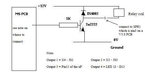
Your fans will already be connected to +12 and then you just connect pin 32 (or 33) to one fan and pin34 (or 35) to the other in the harness (if they aren't already). Condenser fan should be set up to work with Fan Control in TunerStudio. Main fan ends up being just a generic on-off output.
To use the INJ1 and INJ2 on the mainboard for generic PWM outputs, you can do some simple mods to the circuits to make them essentially like the normal TIP120 output circuit.
This *should* be self explanatory.
it should look vaguely like this if you follow all the connections:
Your fans will already be connected to +12 and then you just connect pin 32 (or 33) to one fan and pin34 (or 35) to the other in the harness (if they aren't already). Condenser fan should be set up to work with Fan Control in TunerStudio. Main fan ends up being just a generic on-off output.

Reply
 0
0

0
04-01-2011, 11:16 PM
#22
Elite Member
Thread Starter
iTrader: (3)

Join Date: Apr 2008
Location: Outside Portland Maine
Posts: 2,023
Total Cats: 19
That looks pretty self explanatory, but based on my previous adventures, I will start doing it when my stuff shows up and get mildly confused by something and ask a question about it and then before anybody answers I will figure out the problem while being mildly frustrated, and feel like an idiot for asking the question in the first place.
Hopefully I'll just do it and not have any problems.
Hopefully I'll just do it and not have any problems.
Reply
0
0
04-02-2011, 06:47 PM
#23
Elite Member
Thread Starter
iTrader: (3)
Join Date: Apr 2008
Location: Outside Portland Maine
Posts: 2,023
Total Cats: 19
Which pins on the board are 2 and 3 on Q12 and Q9? I figured it was the right two, but the fans both just stay on whenever the key is on, so I must have done something wrong. I also assumed the two transistors got mounted with the flat part at the top, since that's how all the others get mounted. Is that correct?
Reply
0
0
04-02-2011, 07:34 PM
#25
2 Props,3 Dildos,& 1 Cat
iTrader: (8)
Join Date: Jun 2005
Location: Fake Virginia
Posts: 19,338
Total Cats: 573
Which pins on the board are 2 and 3 on Q12 and Q9? I figured it was the right two, but the fans both just stay on whenever the key is on, so I must have done something wrong. I also assumed the two transistors got mounted with the flat part at the top, since that's how all the others get mounted. Is that correct?
the TIP120s mount just like the other TO220 package components at the heatsink. Again make sure you put mica insulators under them and dont use metal screws (or use the isolator washers).
You caught the 1k resistors in place of R15 and R20?
To test, disconnect power and:
Verify the middle pin of each TIP120 has continuity to the S12 hole (just to the left of the top of the big disc near the connector). Make sure the red probe is on the TIP120 center pin and the black probe is at S12.
Verify the left pin of each TIP120 goes to either pin 21 or 22 of the mainboard's 40-pin connector. "Q1" TIP120 left pin goes to pin 21 (upper left pin nearest the DB9). "Q2" TIP120 left pin goes to pin 22 (just below pin 21)
Verify the right pin connects to ground (heatsink is gnd)
Verify the metal tab on the TIP120 does NOT connect to ground. Meter should read at least "lots of ohms". Probably not less than a few hundred at the very least.
settings:
If your harness is like mine (Inj1 to main fan), then in the outputs menu, you'll have PT1 V3 INJ1 with the following settings:
enabled checkbox checked
power on value 0
trigger value 1
conditions: coolant > threshold 93 hysteresis 7 (or whatever you want)
No additional conditions (or whatever you want)
Under basic/load..
select fan control
fan control ON
Fan Control idles up YES (if you want)
Output Pin INJ BANK 2
idle up delay 200
idle up duty 1.2
fan on temp 97 (or whatever you want)
fan off temp 92 (or whatever you want... should be 3-7 less than above)
allow fan when engine off NO (unless you want)
TPS shutoff whatever you want
TPS hysteresis above minus maybe 10%
VSS shutoff whatever
VSS hysteresis whatever
remember changes to outputs require a burn and power cycle (key off, key on).
you can test by simply checking the coolant temp and setting the coolant trigger value below that. i forget if you have to power cycle just for a temp change or not. that should be evident.
Reply
0
0
04-02-2011, 08:08 PM
#26
Elite Member
Thread Starter
iTrader: (3)
Join Date: Apr 2008
Location: Outside Portland Maine
Posts: 2,023
Total Cats: 19
Thanks for all the info, but I'm using the transistor that came with the mod kit, and I am thinking it might have different output pins than the TIP120 you used. The TIP120, according to the top right of your drawing, has the pins as BCE, while it looks like the PN2222A has the pins CBE. I will try switching them around, though it could get messy pulling them out and bending the short pins and re-doing them.
Reply
0
0
04-02-2011, 10:28 PM
#27
2 Props,3 Dildos,& 1 Cat
iTrader: (8)
Join Date: Jun 2005
Location: Fake Virginia
Posts: 19,338
Total Cats: 573
oh!
I thought I linked you to the TIP120 modkit. That would have been easier to mount for sure.
In any case, once you sort out the transistor, it should work. At this point I'd just pull it and solder some wires to the legs (shrink tube them) and solder the wire to the board.
I thought I linked you to the TIP120 modkit. That would have been easier to mount for sure.
In any case, once you sort out the transistor, it should work. At this point I'd just pull it and solder some wires to the legs (shrink tube them) and solder the wire to the board.
Reply
0
0
04-02-2011, 11:24 PM
#28
Elite Member
Thread Starter
iTrader: (3)
Join Date: Apr 2008
Location: Outside Portland Maine
Posts: 2,023
Total Cats: 19
Well, when I tried earlier the fans did the same thing but the car wouldn't run (all the sensors read horribly wrong) but now it's late and I will try tomorrow with less beer.
Reply
0
0
04-03-2011, 09:32 AM
#29
Elite Member
Thread Starter
iTrader: (3)
Join Date: Apr 2008
Location: Outside Portland Maine
Posts: 2,023
Total Cats: 19
The diodes have something around 11k-ohm resistance, so there isn't direct continuity between the center pin of Q5 and Q1 and S12, there is 11k of resistance. Is that ok? When I plugged this in last night it was horrible. How would this circuit affect inputs like MAP and TPS? (MAP said 165kPa when I turned the key on).
Reply
0
0
04-03-2011, 10:28 AM
#30
2 Props,3 Dildos,& 1 Cat
iTrader: (8)
Join Date: Jun 2005
Location: Fake Virginia
Posts: 19,338
Total Cats: 573
if your meter doesn't have a diode test mode, then you have to test the Q1/Q5 to the non-stripe side of the diode and again from the stripe side of the diodeS to S12.
crazy gauge readings could be a conflict error.
if you suspect the transistors, you can check them (with the diode check mode on your meter..)
if that's unreadable, it's also 2/3 of the way down at
http://www.bcae1.com/repairbasicsfor...pairbasics.htm
crazy gauge readings could be a conflict error.
if you suspect the transistors, you can check them (with the diode check mode on your meter..)
if that's unreadable, it's also 2/3 of the way down at
http://www.bcae1.com/repairbasicsfor...pairbasics.htm
Reply
0
0
04-03-2011, 12:08 PM
#31
Elite Member
Thread Starter
iTrader: (3)
Join Date: Apr 2008
Location: Outside Portland Maine
Posts: 2,023
Total Cats: 19
Well, opposite fans are opposite. Megasquirt clearly has control of them, but they are on and off opposite of whatever MS thinks. As soon as the key is on, both fans come on and stay on until the coolant hits the setpoints, and the fans turn off per the setpoint.
I checked the transistors a bunch of times and I thought sure I had them right, but would wiring them in wrong cause this behavior?
Also, the AC doesn't work. Nothing happens when I press the dash button. Related?
I checked the transistors a bunch of times and I thought sure I had them right, but would wiring them in wrong cause this behavior?
Also, the AC doesn't work. Nothing happens when I press the dash button. Related?
Reply
0
0
04-03-2011, 06:02 PM
#32
2 Props,3 Dildos,& 1 Cat
iTrader: (8)
Join Date: Jun 2005
Location: Fake Virginia
Posts: 19,338
Total Cats: 573
for your fans, is "power on value" 1 or 0? trigger value should be opposite of power on value. megasquirt doesn't know "opposite", it only knows on or off (1 or 0 respectively).
One side of the fan relay is wired to +12 somewhere in the factory harness.
the other side goes to your megasquirt. the way the circuit is now set up, when megasquirt is "on" (1 value), it turns on the transistor which connects the output circuit to ground which energizes the fan relay and turns on the fan.
You can check those two outputs and verify what they're doing when the temp is reached. they should show continuity to ground.
A/C:
I have mine going to JS11 using pin 36 on the mainboard DB37. The other end connects to the refrigerant pressure switch (Mazda pin 4F). All you gotta do (if you haven't) is run a jumper wire on the bottom of the main board from the IGN jumper hole to the JS11 jumper hole. I might have left that off my wiring diagram.
Reply
0
0
 04-03-2011, 06:15 PM
#34
Elite Member
Thread Starter
iTrader: (3)
Join Date: Apr 2008
Location: Outside Portland Maine
Posts: 2,023
Total Cats: 19
I'm pretty stumped. On the stim, one injector light comes on as the temperature goes up, and the other goes off. I can't even tell if I did something wrong with hardware or if there is just a setting off somewhere.
Edit: Posted that without realizing you had replied... disregard.
Edit: Posted that without realizing you had replied... disregard.
Reply
0
0
04-03-2011, 07:56 PM
#35
Elite Member
Thread Starter
iTrader: (3)
Join Date: Apr 2008
Location: Outside Portland Maine
Posts: 2,023
Total Cats: 19
Well, I am still a little stumped. Where do I change the on and off values for the fan controlled by that dialog? One of the fans seems to follow the opposite of whatever that says while the other fan comes on and off opposite of what I expected based on the output setting.
Edit for detail: With power on value set to 0 and trigger value set to 1, the fan does the opposite of what it's set to do. It seems to respond properly when power on is 1 and trigger is 0. I have verified this by checking continuity to ground on the stim, though there seems to be a little bit of voltage or something.
Edit for detail: With power on value set to 0 and trigger value set to 1, the fan does the opposite of what it's set to do. It seems to respond properly when power on is 1 and trigger is 0. I have verified this by checking continuity to ground on the stim, though there seems to be a little bit of voltage or something.
Reply
0
0
04-03-2011, 08:21 PM
#36
Elite Member
Thread Starter
iTrader: (3)
Join Date: Apr 2008
Location: Outside Portland Maine
Posts: 2,023
Total Cats: 19
I just killed something. I've been messing with this thing all day, made no progress, and as soon as I tried the AC after I put the jumper in the car died and megasquirt is now completely unresponsive. It won't connect to the computer, and it doesn't do anything when powered up. I'm about ready to throw this whole thing out the window and set the car on fire.
Reply
0
0
04-03-2011, 10:15 PM
#39
2 Props,3 Dildos,& 1 Cat
iTrader: (8)
Join Date: Jun 2005
Location: Fake Virginia
Posts: 19,338
Total Cats: 573
sure why not...
make a list of everything you need set up or tweaked and include your own pinout diagram (if it's based off mine anyway) to make it easier on us.
you're only 2 days away UPS ground.
PM me your email address and i'll send you my info
make a list of everything you need set up or tweaked and include your own pinout diagram (if it's based off mine anyway) to make it easier on us.
you're only 2 days away UPS ground.
PM me your email address and i'll send you my info
Reply
0
0

Thread
Thread Starter
Forum
Replies
Last Post
SuperSneakySecretSquirrel
Meet and Greet
5
09-06-2015 08:30 PM


