Help me pass emissions
 01-23-2016, 05:00 PM
#21
Junior Member
Thread Starter

Join Date: Mar 2010
Location: Melissa, TX
Posts: 172
Total Cats: 20
Yep. With the car running I see a .2V bounce on the ground just like above, referenced to pin 3, which feeds right into the signal, which bounces along as well. Depending on the sampling frequency of the MS3 on the signal wire it will bounce as well, though the frequency will be corrupted. Time averaging would get rid of it, but .2V is an unacceptable amount of bounce.
Anywhere I can get a schematic of the mainboard? I would think that the input for the 02 sensor should be referenced to this ground, but I am betting it is not based on what I am seeing. I am also curious about what is going on behind pin 3 vs pin2, why I see the bounce on 2 but not 3... A simple differential circuit to clean the input would work, or finding a clean ground source, or correcting the bounce on pin 2...
need to do some research.
*edit* so pin 2 is apparently tied directly to chassis ground, pin 3 must be some sort of special filtered ground. Off to investigate why my chassis ground is bouncing.
Last edited by Ziggo; 01-23-2016 at 05:34 PM.

Reply
 0
0

0
01-23-2016, 07:03 PM
#22
Senior Member
iTrader: (1)

Join Date: Sep 2011
Location: Lambertville, NJ
Posts: 1,215
Total Cats: 74
When you state that your chassis ground is bouncing, what are you using as a reference to measure against? Usually I would think you measure against chassis ground...
Reply
0
0
01-23-2016, 08:39 PM
#23
Junior Member
Thread Starter
Join Date: Mar 2010
Location: Melissa, TX
Posts: 172
Total Cats: 20
So... I checked continuity to chassis and had good connectivity, but as i've learned elsewhere, you really gotta check grounding with a 4 wire meter, which I dont have at home. So in the absence of that I checked the voltage differential between the chassis ground at the ECU and the floor pan with the car running and and found it to be over 1V! I dont know where pins A&B on the ECU are terminating to, but wherever it is, sucks. Similar differential to the head and the grounding points in the engine bay. I noticed that the chassis ground was tied to the jackscrews for the DB-37 connectors when I was replacing the fuse earlier, so I hooked a wire under one of the jackscrews and put the other end in a hole in the floorpan. Voltage differential while running dropped to 200mv or so, and I could certainly improve the grounding. The bouncing is still there, but its much reduced, ~.050V while running now, rather than .2V
After thinking about it, I sent an e-mail out to innovate, the best solution would be to separate the heater and sensor grounds in the LC-2, similar to how the LC-1 was done. That way I can tie the sensor to the clean analog ground, and then the signal generator will be referenced to the same ground that the signal receiver uses. The grounding of the ECU to the chassis is certainly an issue, but there is a basic design issue here with the signal generator and the signal receiver operating from different ground planes.
Reply
0
0
01-23-2016, 10:00 PM
#25
Junior Member
Thread Starter
Join Date: Mar 2010
Location: Melissa, TX
Posts: 172
Total Cats: 20
First you post a useless l2t, then you post that I need to refine my VE table , ignoring the fact that the feedback for tuning the VE table is from the wideband, which currently is returning junk, then you post this, ignoring the fact that I already verified the ground connection between the LC2 and the ECU is good, unless you are proposing that I wire the heater ground for the wideband into the digital ground for the MS3, which is a terrible idea for what should be pretty obvious reasons.
Either you are not reading, you dont really know whats going on, or you are somehow offended by the content or by me and are purposely sabotaging. Whatever the case may be, I would reccomend unsubscribing.
Either you are not reading, you dont really know whats going on, or you are somehow offended by the content or by me and are purposely sabotaging. Whatever the case may be, I would reccomend unsubscribing.
Reply
0
0
01-23-2016, 10:33 PM
#26
Boost Czar


iTrader: (62)
Join Date: May 2005
Location: Chantilly, VA
Posts: 79,488
Total Cats: 4,077
Your lc2 logs are good. It's a clean signal. If there was a problem with the ground then that log would look as bad as the ms's.
The problem seems to lie with the input at the ms. The input circuit on your ms seems to be junking it up. That's where I'd be looking at least. You'll have to reach out to Dimitri for his help here as his ms unique and I couldn't suggest where to probe before and after the input circuit for the signal.
The voltage offset is 100% normal.
Reply
0
0
01-23-2016, 10:54 PM
#27
Junior Member
Thread Starter
Join Date: Mar 2010
Location: Melissa, TX
Posts: 172
Total Cats: 20
Your lc2 logs are good. It's a clean signal. If there was a problem with the ground then that log would look as bad as the ms's.
The problem seems to lie with the input at the ms. The input circuit on your ms seems to be junking it up. That's where I'd be looking at least. You'll have to reach out to Dimitri for his help here as his ms unique and I couldn't suggest where to probe before and after the input circuit for the signal.
The voltage offset is 100% normal.
The problem seems to lie with the input at the ms. The input circuit on your ms seems to be junking it up. That's where I'd be looking at least. You'll have to reach out to Dimitri for his help here as his ms unique and I couldn't suggest where to probe before and after the input circuit for the signal.
The voltage offset is 100% normal.
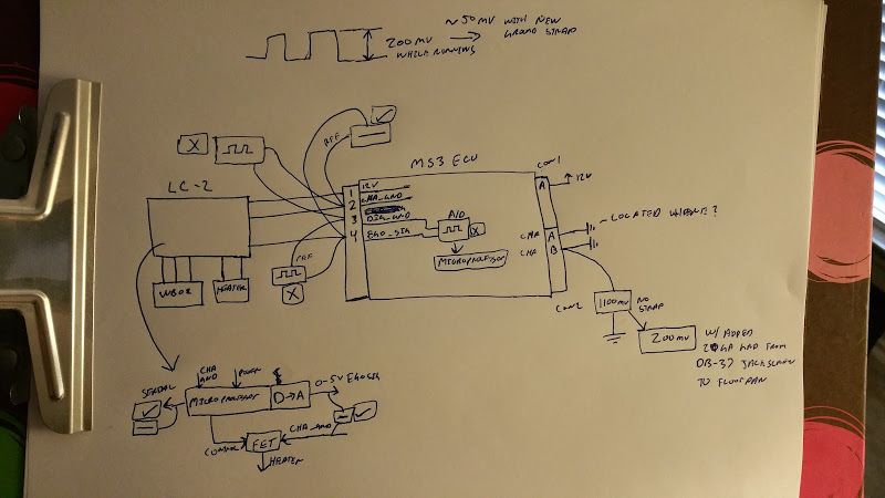
My theory is the problem arises as the LC2 generates the analog output. It generates a voltage relative to the ground it sees. If the ground goes up, the output voltage goes up. The MS3 measures the EGO relative to the digital ground, which doesn't have the bounce the ground of the LC2 has, so the MS3 logs the bounce.
Solutions:
Get rid of the bounce on chassis ground
Feed the LC2 the digital ground of the MS3
Differential Op Amp with zero gain to clean up the EGO signal into the MS3
I'm a mechanical engineer, mostly because I hated electrical issues.
Reply
0
0
01-24-2016, 04:03 AM
#28
Elite Member
iTrader: (10)
Join Date: Jun 2006
Location: Athens, Greece
Posts: 5,976
Total Cats: 355
Pin 2 is the I/O ground, meaning all MS3 outputs sink current through this ground, hence why you see noise it.
It's rather obvious why I use a different ground for the I/O, and a different one for the digital/analog logic, right?
Do the following test with the engine off, ignition on: disconnect the idle valve and see if the issue goes away. It's the only current pulsing device operating while the engine is not running.
Reply
0
0
01-24-2016, 08:14 AM
#29
Junior Member
Thread Starter
Join Date: Mar 2010
Location: Melissa, TX
Posts: 172
Total Cats: 20
Pin 2 is the I/O ground, meaning all MS3 outputs sink current through this ground, hence why you see noise it.
It's rather obvious why I use a different ground for the I/O, and a different one for the digital/analog logic, right?
Do the following test with the engine off, ignition on: disconnect the idle valve and see if the issue goes away. It's the only current pulsing device operating while the engine is not running.
It's rather obvious why I use a different ground for the I/O, and a different one for the digital/analog logic, right?
Do the following test with the engine off, ignition on: disconnect the idle valve and see if the issue goes away. It's the only current pulsing device operating while the engine is not running.
I already disconnected the IAC valve with the key on and engine off and it made no difference. I also disconnected the VVT actuator for good measure and the bounce remained. I am really baffled by what could be causing it.
Reply
0
0
01-24-2016, 08:39 AM
#30
Senior Member
iTrader: (1)
Join Date: Sep 2011
Location: Lambertville, NJ
Posts: 1,215
Total Cats: 74
Sorry- I can't tell you what's wrong here. I can only give general troubleshooting advice. In situations like you're in right now, it helps me to draw a schematic of the problem. Aids with visualization. Also helps explaining the problem to others whenposted.
Reply
0
0
01-24-2016, 09:40 AM
#31
Junior Member
Thread Starter
Join Date: Mar 2010
Location: Melissa, TX
Posts: 172
Total Cats: 20
Good idea. Looking at it, I have not checked to see if I see the bounce on the 12V line, maybe the voltage regulator is causing the 12V to bounce, and thus the ground to bounce along with it. Seeing as without the strap I am really floating away from the chassis it could explain the problem. I am off to do my real job for a few hours.
Reply
0
0
01-24-2016, 10:08 AM
#32
Tweaking Enginerd
iTrader: (2)

Join Date: Mar 2013
Location: Boulder, CO
Posts: 1,770
Total Cats: 350
I think you have started down the right path of looking for ground currents. I would consider the possibility that the WB heater current is the culprit. As drawn up there ^ all of your heater current is flowing through the reference plane of the MS. A few suggestions:
- Decouple the sensor return to the chassis with a low ESR capacitor
- Add a common mode wrap on the lines running to the WB
- Decouple both the 12V and the signal out of the WB to their local return with capacitors
- Provide a local (to the WB) low impedance DC path from the sensor directly to the chassis return. Run a second low current return reference back to the aquisition system. You could force the heater currents through the low Z path with a common mode choke on the power lines and then another on the signal/reference lines (assumes high z input on the DAQ)
Reply
0
0
01-24-2016, 10:26 AM
#33
Tweaking Enginerd
iTrader: (2)
Join Date: Mar 2013
Location: Boulder, CO
Posts: 1,770
Total Cats: 350
WRT the emissions...
The CAT needs O2 to convert CO into CO2. Lean/retard results in best no-CAT content. Stoich/retard with CAT. If too rich, you wont have enough O2 to convert the HC and CO. You can get more O2 by increasing NOx
Heat is needed for the reaction. -> retard
The CAT needs O2 to convert CO into CO2. Lean/retard results in best no-CAT content. Stoich/retard with CAT. If too rich, you wont have enough O2 to convert the HC and CO. You can get more O2 by increasing NOx
Heat is needed for the reaction. -> retard
Reply
0
0
01-24-2016, 11:47 AM
#34
Junior Member
Thread Starter
Join Date: Mar 2010
Location: Melissa, TX
Posts: 172
Total Cats: 20
WRT the emissions...
The CAT needs O2 to convert CO into CO2. Lean/retard results in best no-CAT content. Stoich/retard with CAT. If too rich, you wont have enough O2 to convert the HC and CO. You can get more O2 by increasing NOx
Heat is needed for the reaction. -> retard
The CAT needs O2 to convert CO into CO2. Lean/retard results in best no-CAT content. Stoich/retard with CAT. If too rich, you wont have enough O2 to convert the HC and CO. You can get more O2 by increasing NOx
Heat is needed for the reaction. -> retard
Honestly I could probably get a low mileage waver at this point, and maybe with the bias corrected it would pass even while bouncing, but it's now a tuning issue. Thread title should probably be "LC2 grounding scheme sucks, LC1 was better and here is why" since the LC1 has separate ground wires for the heater and the signal.
Reply
0
0
01-24-2016, 12:09 PM
#37
Junior Member
Thread Starter
Join Date: Mar 2010
Location: Melissa, TX
Posts: 172
Total Cats: 20
I'm not saying the LC2 can't work, but from a signal integrity standpoint it's a poor design. Not to say there isnt something else wrong with my car, but using the chassis ground for a signal ground is pretty poor form. I've done a fair amount of EMI testing in my day job and **** like this always causes issues. I bet you could take your clean signal and drive somewhere with alot of EMI, like the top of Mt Wilson in CA, and you would pickup the noise in your signal.
Reply
0
0
01-24-2016, 12:54 PM
#39
Just out if curiosity, what alternator are you using?
I'm not saying the LC2 can't work, but from a signal integrity standpoint it's a poor design. Not to say there isnt something else wrong with my car, but using the chassis ground for a signal ground is pretty poor form. I've done a fair amount of EMI testing in my day job and **** like this always causes issues. I bet you could take your clean signal and drive somewhere with alot of EMI, like the top of Mt Wilson in CA, and you would pickup the noise in your signal.
I'm not saying the LC2 can't work, but from a signal integrity standpoint it's a poor design. Not to say there isnt something else wrong with my car, but using the chassis ground for a signal ground is pretty poor form. I've done a fair amount of EMI testing in my day job and **** like this always causes issues. I bet you could take your clean signal and drive somewhere with alot of EMI, like the top of Mt Wilson in CA, and you would pickup the noise in your signal.
Reply
1
1
01-24-2016, 12:59 PM
#40
Boost Czar
iTrader: (62)
Join Date: May 2005
Location: Chantilly, VA
Posts: 79,488
Total Cats: 4,077
My theory is the problem arises as the LC2 generates the analog output. It generates a voltage relative to the ground it sees. If the ground goes up, the output voltage goes up. The MS3 measures the EGO relative to the digital ground, which doesn't have the bounce the ground of the LC2 has, so the MS3 logs the bounce.
Have you determined that the LC2 isnt itself outputting junk on the yellow analog one output? or that the MS itself is doing something to the signal after it's own input circuit?
i was finally able to log at your log, it looks like a lot going "oddly". This was during the emissions run?
what's your setup like? can you post your actual msq?
Last edited by Braineack; 01-24-2016 at 01:12 PM.
Reply
0
0


