Help tracking down MS3 wiring issues/diagram
 03-17-2014, 08:51 PM
#61
Elite Member
Thread Starter

Join Date: Oct 2013
Location: Cedar City, UT
Posts: 2,764
Total Cats: 951
OK I hope this helps to...this took me a while. Correlated all pins on the DB37 connectors to their associated spots on the DIYBOB board
Upper DP37 Connector
Pin 1 to 4U=green=F-Idle
Pin 2=unused
Pin 3=Ground
Pin 4 to 4V=Blue=TPS-SIG
Pin 5 to 2I=White/Blue=IAC1-B
Pin 6 to 1G=IAC-2A
Pin 7 to 2H=Green/White=IAC2-B
Pin 8=Ground
Pin 9 to 1V=green/white=IAC2-B
Pin 10 to 2F=Blue/White= IAC1-A
Pin 11 to 4W=Green=F-Idle
Pin 12=Ground
Pin 13=unused
Pin 14 to 2J=Brown=PIN36
Pin 15=unused
Pin 16 to 1R=Blue/white=IAC1-A
Pin 17=Ground
Pin 18=Soldered to Pin 16 Ground
Pin 19 to 2D=Pink=O2
Pin 20-22=Unused
Pin 23 to 2K=Purple=Fuel Pump
Pin 24 to 1H=Brown=PIN36
Pin 25 to 1B=White/Blue=IAC1-B
Pin 26-28=unused
Pin 29 to 1Q=Orange=IAT
Pin 30=Unused
Pin 31 to 2B=Grey=TPS-VREF
Pin 32-36=Unused
Pin 37 to 1J=Yellow=Coolant
Lower DB37 Connector
Pin 1-8=unused
Pin 9-12=Black=Ground
Pin 13-19=unused
Pin 20 to 4P=orange=IAT
pin 21 to 4Q=Yellow=Coolant
Pin 22 to 4L=blue=TPS-SIG
Pin 23 to 4N=Pink=O2
Pin 24 to 4E=white=shield wire?
Pin 25=unused
Pin 26 to 1N=Grey=TPS-VREF
Pin 27 goes to a 1 pin connector
pin 28 to 1B=red=12VDC also has a green wire soldered to it that loops to a hole in the board right behind it
Pin 28-36=unused
Pin 37=purple=Fuel Pump===ThisGoes to green circuit board behind 1A-1V pins
1C=green=soldered to green circuit board behind 1A-1V
Unused pins on DIYBOB
4I/4K/4H/4O=Unused
4S=Unused
4Y=Unused
4F/4H/4j=Unused
4R/4T=Unused
1A-Unused
1E=Unused
1I/1K/1M/1O-unused
1S/1U-Unused
1D/1F=unused
1L=unused
1P=unused
1T=unused

Reply
 0
0

0
03-18-2014, 08:42 AM
#62
Boost Czar


iTrader: (62)
Join Date: May 2005
Location: Chantilly, VA
Posts: 79,483
Total Cats: 4,076
I just want to remind you that you are the worst wiring documenter ever. Like maybe in history.
you're making this so hard.
Why cant you do this for me:
2A - Goes to green breakout board
2B - Goes to MS3X-Pin31
2C - Goes to green breakout board
ETC.
AND on that note, GET THE LABELS CORRECT.
2B does NOT go to Pin31 of the upper (ms3x) connector. That's PT4 Logic Output and I would have never built a unit using that output.
I'm assuming you got your labels assbackwards and it's actually Pin26 and it's the Tacho output.
I dont care about the colors. I dont I dont about the labels. I dont care about the wires on the other 2 connectors. Just tell me where the damn wires on the 2A-2P go!
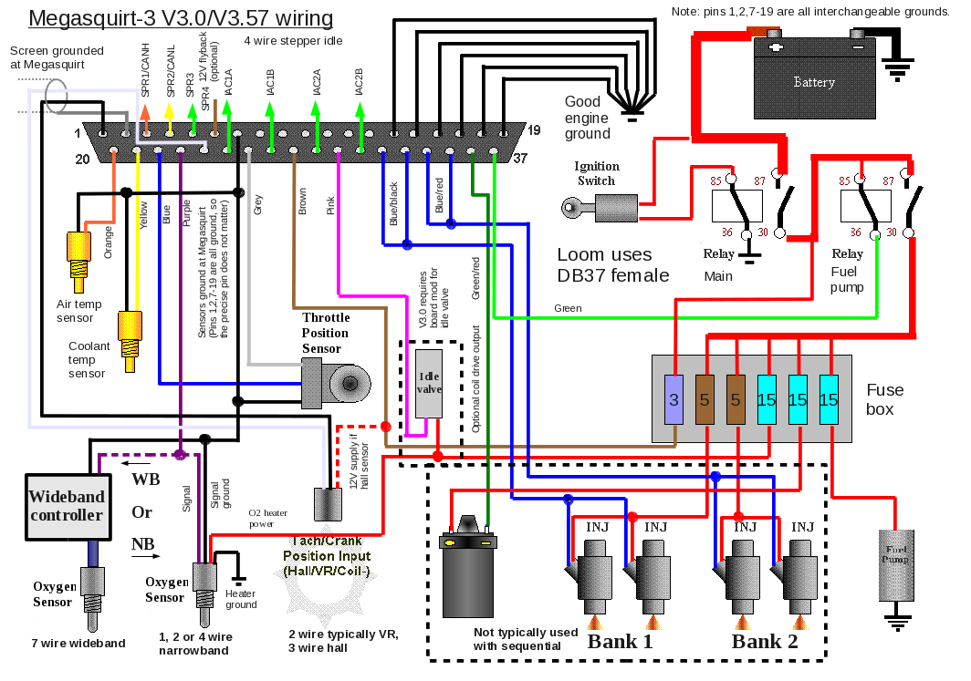
look: Megasquirt-3 MS3 Hardware Manual
These are the only constants, so if you wanna figure out how your 16-pin connector is pinned, you must trace it back to those outputs from the MS unit itself.
All I need for you to do is tell me where the **** 2A-2P go on the harness pins. that's is. incredibly simply request and should take you 2 mins to track all the wires. CORRECTLY.
What you gave me is incorrect as the pins you suggests the wires go don't make a lick of sense.
honestly. im in a mood now and dont want to be helpful. You can you the diagrams I linked and figure it all out yourself.
And dont leave out 2E and 2G and 2L off the list this time.
you're making this so hard.
Why cant you do this for me:
2A - Goes to green breakout board
2B - Goes to MS3X-Pin31
2C - Goes to green breakout board
ETC.
AND on that note, GET THE LABELS CORRECT.
2B does NOT go to Pin31 of the upper (ms3x) connector. That's PT4 Logic Output and I would have never built a unit using that output.
I'm assuming you got your labels assbackwards and it's actually Pin26 and it's the Tacho output.
I dont care about the colors. I dont I dont about the labels. I dont care about the wires on the other 2 connectors. Just tell me where the damn wires on the 2A-2P go!
look: Megasquirt-3 MS3 Hardware Manual
These are the only constants, so if you wanna figure out how your 16-pin connector is pinned, you must trace it back to those outputs from the MS unit itself.
All I need for you to do is tell me where the **** 2A-2P go on the harness pins. that's is. incredibly simply request and should take you 2 mins to track all the wires. CORRECTLY.
What you gave me is incorrect as the pins you suggests the wires go don't make a lick of sense.
honestly. im in a mood now and dont want to be helpful. You can you the diagrams I linked and figure it all out yourself.
And dont leave out 2E and 2G and 2L off the list this time.
Reply
0
0
03-18-2014, 08:51 AM
#63
Elite Member
Thread Starter
Join Date: Oct 2013
Location: Cedar City, UT
Posts: 2,764
Total Cats: 951
Apologies all around brain, really, I was simply trying to be helpful by giving an exact picture of the DB37 connectors. ...
I'll upload the DB12 pinout and if you feel differently later I'd appreciate it. If not I appreciate the help given so far.
Since I didn't install it myself, and no past experience with it, it is quite literally like a retarded person learning a different language.
Sorry for the frustration dude.
I'll upload the DB12 pinout and if you feel differently later I'd appreciate it. If not I appreciate the help given so far.
Since I didn't install it myself, and no past experience with it, it is quite literally like a retarded person learning a different language.
Sorry for the frustration dude.
Reply
0
0
03-18-2014, 09:26 AM
#65
Elite Member

Join Date: Mar 2006
Location: Schwarzenberg, Germany
Posts: 1,553
Total Cats: 101
O.K. Jeff, let's try to confirm the standard things first:
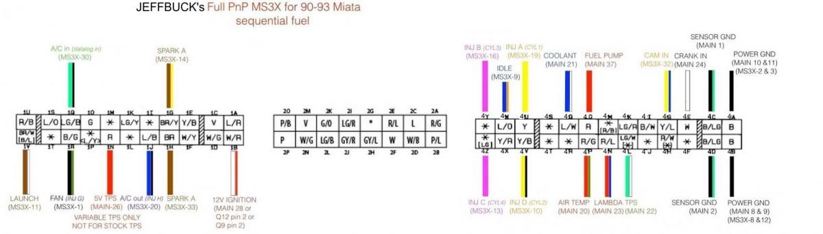
I will be using this picture out of Franks site,

First of all - your connector 4 equals the connector 2 on this picture - as the 90-93 of course only has 2 connectors OEM.
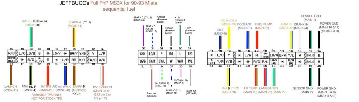
and I will be using this two pictures from the MS3 documentation:

I will be using this picture out of Franks site,
First of all - your connector 4 equals the connector 2 on this picture - as the 90-93 of course only has 2 connectors OEM.
and I will be using this two pictures from the MS3 documentation:
OK I hope this helps to...this took me a while. Correlated all pins on the DB37 connectors to their associated spots on the DIYBOB board
Upper DP37 Connector
Pin 1 to 4U=green=F-Idle-please don't care for what is written on the wires - - that should be your injector for cyl 1 - equals INJ G on the MS3X
Pin 2=unused
Pin 3=Ground -correct - MS3X ground connection
Pin 4 to 4V=Blue - -that should be your injector for cyl 2 - equals INJ F on the MS3X
Pin 5 to 2I=White/Blue - -equals FLEX fuel input port on the MS3X - please look up in Tuner Studio in your MSQ - which function is connected with that output port
Pin 6 to 1G - - 1G should be your Spark A - but that doesn't match up with the PIN6 on the MS3X - because that is the boost output
Pin 7 to 2H=Green/White - -equals INJ E output port on the MS3X - please look up in Tuner Studio in your MSQ - which function is connected with that output port
Pin 8=Ground -correct - MS3X ground connection
Pin 9 - please re-check to 1V=green/white - -should be your launch input - but has to be connected to pin 11 on the MS3X connector, not 9
Pin 10 to 2F=Blue/White - -equals INJ D output port on the MS3X - please look up in Tuner Studio in your MSQ - which function is connected with that output port
Pin 11 to 4W=Green - -idle, but not correct - your idle valve pin 4W should be connected to pin 9
Pin 12=Ground -correct - MS3X ground connection
Pin 13=unused
Pin 14 to 2J=Brown=PIN36 - equals output SPK F on the MS3X
Pin 15=unused
Pin 16 to 1R=Blue/white - -should be your Fan switch - equals output INJ B on the MS3X
Pin 17=Ground -correct - MS3X ground connection
Pin 18=Soldered to Pin 16 Ground
Pin 19 to 2D=Pink - -equals INJ A output port on the MS3X - please look up in Tuner Studio in your MSQ - which function is connected with that output port
Pin 20-22=Unused
Pin 23 to 2K=Purple - -equals EXT MAP input port on the MS3X - please look up in Tuner Studio in your MSQ - which function is connected with that output port
Pin 24 to 1H=Brown -- 1H should be your Spark B - but that doesn't match up with the PIN24 on the MS3X - because that is the NITROUS 1 output
Pin 25 to 1B - i think this should be 2B=White/Blue - -equals NITROUS 2 output port on the MS3X - please look up in Tuner Studio in your MSQ - which function is connected with that output port
Pin 26-28=unused
Pin 29 to 1Q=Orange - - 1Q should be your A/C in- but that doesn't match up with the PIN29 on the MS3X - because that is the +12V Nitrous in input
Pin 30=Unused
Pin 31 to 2B - please re-check=Grey - -equals PT4 logic output port on the MS3X - please look up in Tuner Studio in your MSQ - which function is connected with that output port
Pin 32-36=Unused
Pin 37 to 1J=Yellow - - 1J should be your A/C output but that doesn't match up with the PIN37 on the MS3X - because that is a spark output
I think you didn't look at the numbers (stamped in at the connector) of the DB37 for the MS3X correctly, because it looks mirrored to me - we might have to redo the whole upper DB37 connector
Lower DB37 Connector
Pin 1-8=unused
Pin 9-12=Black=Ground
Pin 13-19=unused
Pin 20 to 4P=orange=IAT - -your IAT sensor connection to the MS3
pin 21 to 4Q=Yellow=Coolant - -your coolant sensor connection to the MS3
Pin 22 to 4L=blue=TPS-SIG - -your TPS sensor signal connection to the MS3
Pin 23 to 4N=Pink=O2 - -your O2 sensor connection to the MS3
Pin 24 to 4E=white=shield wire? - -your CRANK sensor connection to the MS3
Pin 25=unused
Pin 26 to 1N=Grey=TPS-VREF - -your your TPS +5V connection to the MS3
Pin 27 goes to a 1 pin connector - -equals IAC1B output port on the MS3 - please look up in Tuner Studio in your MSQ - which function is connected with that output port
pin 28 to 1B=red=12VDC also has a green wire soldered to it that loops to a hole in the board right behind it - your 12V connection to the MS3
Pin 28-36=unused
Pin 37=purple=Fuel Pump===ThisGoes to green circuit board behind 1A-1V pins - -this is your fuel pump output on the MS3
1C=green=soldered to green circuit board behind 1A-1V - ? something to do with fuel pump output on the MS3 ?
We don't care for unused ports...
Reply
0
0
03-18-2014, 10:14 AM
#66
Elite Member
Join Date: Mar 2006
Location: Schwarzenberg, Germany
Posts: 1,553
Total Cats: 101
To keep the Brain happy - here is a nice wiring diagramm for your car Jeff - I will update this as we go (whenever I get the time for it) - first I will update the MS3X part - once you get the pinout sorted...
As you obviously mirrored the pins on the MS3X - here is what I think should be the correct wiring.
I think we found all the missing links now - I will re-do your wiring scheme picture tomorrow...
As you obviously mirrored the pins on the MS3X - here is what I think should be the correct wiring.
OK I hope this helps to...this took me a while. Correlated all pins on the DB37 connectors to their associated spots on the DIYBOB board
Upper DP37 Connector
Pin 19 to 4U - - that should be your injector for cyl 1 - equals INJ A on the MS3X
Pin 18unused - - equals SPK G on the MS3X
Pin 17- MS3X ground connection
Pin 16 to 4V - - that should be your injector for cyl 2 - equals INJ B on the MS3X
Pin 15 to 2I - - I guess this is one of the sequential spark extra wires - equals SPARK C on the MS3X
Pin 14 to 1G - - this is your Spark A - equals SPARK A on the MS3X
Pin 13 to 2H - - I guess this is one of the sequential injection extra wires - equals INJ C output port on the MS3X
Pin 12=Ground - MS3X ground connection
Pin 11 to 1V - -your LAUNCH input - equals Launch in on the MS3X
Pin 10 to 2F - -I guess this is one of the sequential injection extra wires - equals INJ D output port on the MS3X
Pin 9 to 4W - -your IDLE output - equals Idle on the MS3X
Pin 8=Ground - -MS3X ground connection
Pin 7=unused - - equals INJ E on the MS3X
Pin 6 to 2J - - - your boost output - equals BOOST output on the MS3X
Pin 5=unused - - equals Flex fuel input on the MS3X
Pin 4 to 1R - -should be your Fan switch - equals output INJ F on the MS3X
Pin 3=Ground - MS3X ground connection
Pin 2=Ground - MS3X ground connection
Pin 1 to 2D - -equals INJ G output port on the MS3X - please look up in Tuner Studio in your MSQ - which function is connected with that output port
Pin 37-35=Unused
Pin 34 to 2K - - this is your Spark D - equals SPARK D on the MS3X
Pin 33 to 1H - - this is your Spark B - equals SPARK B on the MS3X
Pin 32 to 1B -re-check please - -this is your CAM input - equals CAM input port on the MS3X
Pin 31-29=unused
Pin 28 to 1Q=Orange - - this is your A/C in- equals the TABLESW IN port on the MS3X
Pin 27=Unused
Pin 26 to 2B - please re-check=Grey - - that is your Tacho output - equals TACHO output port on the MS3X
Pin 25-21=Unused
Pin 20 to 1J - - this is your A/C output - equals output INJ H on the MS3X
Lower DB37 Connector
Pin 1-8=unused
Pin 9-12=Black=Ground
Pin 13-19=unused
Pin 20 to 4P=orange=IAT - -your IAT sensor connection to the MS3
pin 21 to 4Q=Yellow=Coolant - -your coolant sensor connection to the MS3
Pin 22 to 4L=blue=TPS-SIG - -your TPS sensor signal connection to the MS3
Pin 23 to 4N=Pink=O2 - -your O2 sensor connection to the MS3
Pin 24 to 4E=white=shield wire? - -your CRANK sensor connection to the MS3
Pin 25=unused
Pin 26 to 1N=Grey=TPS-VREF - -your your TPS +5V connection to the MS3
Pin 27 goes to a 1 pin connector - -equals IAC1B output port on the MS3 - please look up in Tuner Studio in your MSQ - which function is connected with that output port
pin 28 to 1B=red=12VDC also has a green wire soldered to it that loops to a hole in the board right behind it - your 12V connection to the MS3
Pin 28-36=unused
Pin 37=purple=Fuel Pump===ThisGoes to green circuit board behind 1A-1V pins - -this is your fuel pump output on the MS3
1C=green=soldered to green circuit board behind 1A-1V - ? something to do with fuel pump output on the MS3 ?
Last edited by Zaphod; 03-18-2014 at 10:47 AM.
Reply
0
0
03-18-2014, 11:40 AM
#68
Elite Member
Thread Starter
Join Date: Oct 2013
Location: Cedar City, UT
Posts: 2,764
Total Cats: 951
2A goes to green breakout board
2C goes to green breakout board
2E Ground goes to green breakout board
2G Ground goes to green breakout board
2I to MS3x-Pin15
2K to MS3x-Pin34
2B to MS3x-Pin26
2D to MS3x-Pin1
2F to MS3x-Pin10
2H to MS3x-Pin13
2J to MS3x-Pin6
2C goes to green breakout board
2E Ground goes to green breakout board
2G Ground goes to green breakout board
2I to MS3x-Pin15
2K to MS3x-Pin34
2B to MS3x-Pin26
2D to MS3x-Pin1
2F to MS3x-Pin10
2H to MS3x-Pin13
2J to MS3x-Pin6
Reply
0
0
03-18-2014, 01:49 PM
#72
Elite Member
Join Date: Mar 2006
Location: Schwarzenberg, Germany
Posts: 1,553
Total Cats: 101
Don't tell me you didn't change them sometime inbetween, they have changed to the correct ones now... ;-)
O.K. let's try
O.K. let's try
2A goes to green breakout board +12V source maybe for the WBO2 or such?
2C goes to green breakout board +12V source maybe for the WBO2 or such?
2E Ground goes to green breakout board - a common ground with the MS3 and MS3X grounds, well could be for your WB or such - Brain?
2G Ground goes to green breakout board - a common ground with the MS3 and MS3X grounds, well could be for your WB or such - Brain?
2I to MS3x-Pin15 - SPARK C - which cylinder would that be?
2K to MS3x-Pin34 - SPARK D - which cylinder would that be?
2B to MS3x-Pin26 - Tacho output
2D to MS3x-Pin1 your VICS output - equals INJ G output port on the MS3X
2F to MS3x-Pin10 INJ D output port on the MS3X - seq. inj. for cylinder 2 (?)
2H to MS3x-Pin13 INJ C output port on the MS3X - seq. inj. for cylinder 4 (?)
2J to MS3x-Pin6 - your boost output - equals BOOST output on the MS3X
Last edited by Zaphod; 03-19-2014 at 06:17 AM.
Reply
0
0
03-18-2014, 02:45 PM
#74
Elite Member
Join Date: Mar 2006
Location: Schwarzenberg, Germany
Posts: 1,553
Total Cats: 101
That doesn't matter anyway, I think we got them right now - we just need Braineack to clear some of the things for us, I think he has a standart wiring scheme for those things...
Edit: Confirmed and changed in post 72 that 2A and 2C are the two +12V sources
Edit: Confirmed and changed in post 72 that 2A and 2C are the two +12V sources
Last edited by Zaphod; 03-19-2014 at 03:06 AM.
Reply
0
0
03-19-2014, 04:40 AM
#75
Elite Member
Join Date: Mar 2006
Location: Schwarzenberg, Germany
Posts: 1,553
Total Cats: 101
Here is the updated wiring scheme:
Things to confirm:
- do you have a wire on 4G - that should be your CAM input?
- which Spark is for which cylinder on the connector 2? (Braineack?)
- are the cylinders for the injectors 3 and 4 on connector 2 labelled correctly?
@Braineack - what circuit would you have build here on the breakout board?
@Jeffbucc - I will send you a PM with may mail address - please send me you current MSQ from the MS3.
EDIT:
[COLOR="Red"]Just had a look at the MSQs -
as per setting the Injectors are paired as follows:
INJ A - Cyl. 1
INJ B - Cyl. 3
INJ C - Cyl. 4
INJ D - Cyl. 2
I changed this in the wiring scheme
Also the VICS output is on connector 2 - 2D - using INJ G output on the MS3X.
CAM sensor on MS3X pin 32 (CAM IN)
Last edited by Zaphod; 03-19-2014 at 08:43 AM.
Reply
0
0
03-19-2014, 06:02 AM
#76
Elite Member
Thread Starter
Join Date: Oct 2013
Location: Cedar City, UT
Posts: 2,764
Total Cats: 951
Things to confirm:
- do you have a wire on 4G - that should be your CAM input?
- which Spark is for which cylinder on the connector 2? (Braineack?)
- are the cylinders for the injectors 3 and 4 on connector 2 labelled correctly?
@Jeffbucc - I will send you a PM with may mail address - please send me you current MSQ from the MS3.
-Yes which goes to Pin32 on the upper connector
-I never removed the injectors from the engine during the entire build. Only the COP harness was removed.
I'm not sure why the COP had 2&4 as the sequential input as from what most have stated, 3&4 are paired together.
Reply
0
0
03-19-2014, 07:05 AM
#77
Elite Member
Join Date: Mar 2006
Location: Schwarzenberg, Germany
Posts: 1,553
Total Cats: 101
So we know where your CAM input is... 
Changed in the wiring scheme above.
And it tells me that this was changed shortly before the theft/crash because the "older" MSQs (from July 13 and the Currenttune.msq) are using JS10 as CAM input.
You will have to use the MSQ from August 2013.
I still can't wrap my head around, what the 1-wire connector on pin 27 of the lower DB37 Main plug should be - it equals output IAC1B of the MS3 which has no function as it seems
Sniplet of the MS3 input/output usage chart:
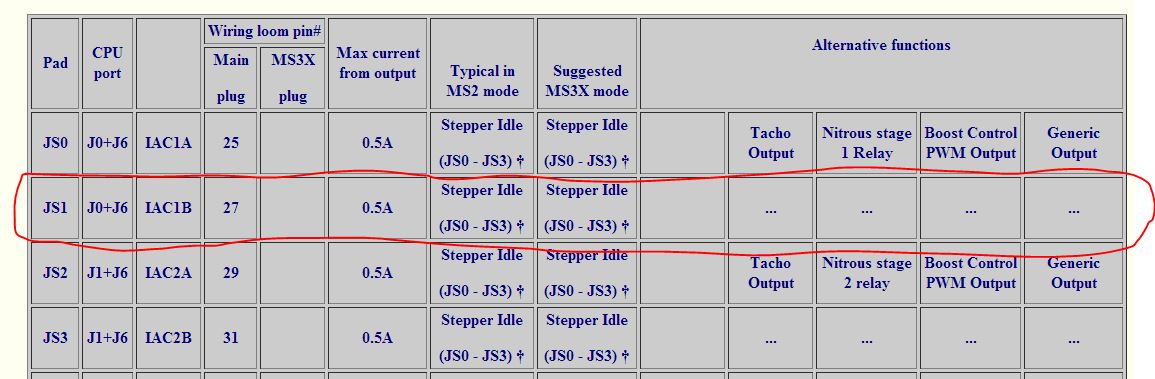
Another Ninja edit:
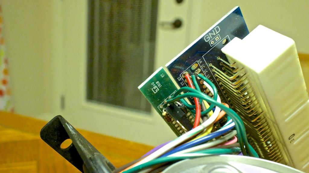
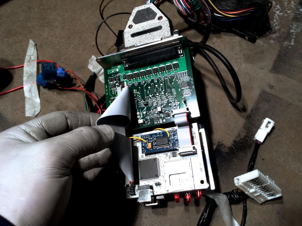
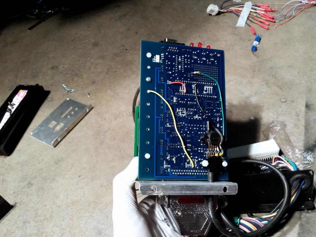
This is your Knock sensor input as per this pictures! See the yellow wire going from IAC1B port to the knock module on top of the MS3 daughter board
Changed in the wiring scheme above.
And it tells me that this was changed shortly before the theft/crash because the "older" MSQs (from July 13 and the Currenttune.msq) are using JS10 as CAM input.
You will have to use the MSQ from August 2013.
I still can't wrap my head around, what the 1-wire connector on pin 27 of the lower DB37 Main plug should be - it equals output IAC1B of the MS3 which has no function as it seems
Sniplet of the MS3 input/output usage chart:
Another Ninja edit:
This is your Knock sensor input as per this pictures! See the yellow wire going from IAC1B port to the knock module on top of the MS3 daughter board
Last edited by Zaphod; 03-19-2014 at 07:30 AM.
Reply
0
0
03-19-2014, 08:36 AM
#79
Elite Member
Join Date: Mar 2006
Location: Schwarzenberg, Germany
Posts: 1,553
Total Cats: 101
@Jeff - when you re-did your COP harness did you leave the two extra wires for the sequential spark in or did you wire as Wasted spark?
@Brain- if the Ignition is also sequential I guess the firing order is the same as the injectors - so 1-3-4-2
So that for the Ignition the setup would be: (Braineack - can you please have a look at the, because I don't have wired for seq. ignition up to now...)
SPARK A - IGN cyl 1 - Connector pin 1G
SPARK B - IGN cyl 3 - Connector pin 1H
SPARK C - IGN cyl 4 - Connector pin 2I
SPARK D - IGN cyl 2 - Connector pin 2K
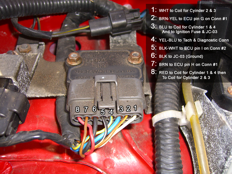
So I think you did your COP harness correctly, Jeff 1&3 at the OEM wiring, 2&4 at the extra wiring on the 12pin connector.
(Please do check, that cyl 1 connects with the brown/yellow wire at the igniter connector and cyl 3 with the brown wire.)
@Brain- if the Ignition is also sequential I guess the firing order is the same as the injectors - so 1-3-4-2
So that for the Ignition the setup would be: (Braineack - can you please have a look at the, because I don't have wired for seq. ignition up to now...)
SPARK A - IGN cyl 1 - Connector pin 1G
SPARK B - IGN cyl 3 - Connector pin 1H
SPARK C - IGN cyl 4 - Connector pin 2I
SPARK D - IGN cyl 2 - Connector pin 2K
So I think you did your COP harness correctly, Jeff 1&3 at the OEM wiring, 2&4 at the extra wiring on the 12pin connector.
(Please do check, that cyl 1 connects with the brown/yellow wire at the igniter connector and cyl 3 with the brown wire.)
Last edited by Zaphod; 03-19-2014 at 08:50 AM.
Reply
0
0
03-19-2014, 08:37 AM
#80
Boost Czar
iTrader: (62)
Join Date: May 2005
Location: Chantilly, VA
Posts: 79,483
Total Cats: 4,076
spark fuel is both wired the same: abcd = 1342
I'd probably change the harness slightly so that the knock input went to the center connector (one of the extra 12v or grounds) that way you don't have some random wire dangling.
you boost control and idle control need flyback didoes added as well.
I'd probably change the harness slightly so that the knock input went to the center connector (one of the extra 12v or grounds) that way you don't have some random wire dangling.
you boost control and idle control need flyback didoes added as well.
Reply
0
0


