Help wiring the MS2
 02-26-2014, 01:34 PM
#1
Junior Member
Thread Starter
iTrader: (2)

Join Date: Mar 2013
Location: Livermore, CA
Posts: 138
Total Cats: -18
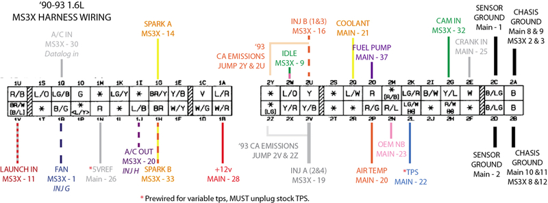
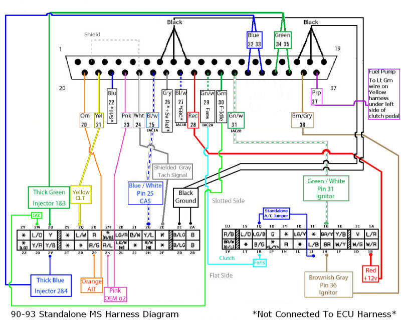
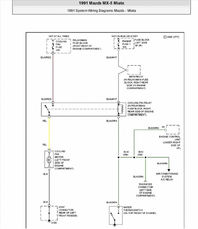
So these are the diagrams I've been using to wire this up so far:
And this shows the ACTUAL pinout of the premade DB37 connector I have. It apparently has changed since the above diagram was made.

The internal mods to the MS 3.57 that I have done are:
1K ohm resistor between JS10 and PAD7
470 ohm resistor from PAD7 to the +5V hole
0.1microfarad Capacitor between JS8 and GND
470 ohm resistor across the two terminals of R57
So, where I'm at right now is, since the grounds are different between the two DB37 connectors I wasn't sure exactly how to hook them up, and I wasn't sure if it really mattered where I hook them up. Right now I have pins 17, 18, and 19 from the DB37 hooked up to 2A on the harness, pins 15 and 16 hooked up to 2B, and the black/white sensor ground wire from PIN 7 hooked up to 2C.
I don't have spark output B hooked up yet because it now comes out on the DB15 connector. I don't see the Gn/W wire on the DB37 for the fans so I'm guessing that now comes out on the DB15 connector as well but I do not know where? Lastly, the only other thing I don't have hooked up yet is the crank in for Pin 2E, the wire is supposed to be the twisted shielded wire, but this wire is actually a black and white wire twisted together so I'm not sure which of the two or if both get hooked up to the connector. Also, I'm assuming that the bare shield wire in there is NOT supposed to be hooked up to a ground or anything, right?
I appreciate any help! I was able to load firmware to the MS yesterday finally but now I have to fix my laptop because for some reason it crashes every time I load tunerstudio except in Safe mode, but it won't communicate through the COM port when it's in safe mode the problems never end...
And this shows the ACTUAL pinout of the premade DB37 connector I have. It apparently has changed since the above diagram was made.
The internal mods to the MS 3.57 that I have done are:
1K ohm resistor between JS10 and PAD7
470 ohm resistor from PAD7 to the +5V hole
0.1microfarad Capacitor between JS8 and GND
470 ohm resistor across the two terminals of R57
So, where I'm at right now is, since the grounds are different between the two DB37 connectors I wasn't sure exactly how to hook them up, and I wasn't sure if it really mattered where I hook them up. Right now I have pins 17, 18, and 19 from the DB37 hooked up to 2A on the harness, pins 15 and 16 hooked up to 2B, and the black/white sensor ground wire from PIN 7 hooked up to 2C.
I don't have spark output B hooked up yet because it now comes out on the DB15 connector. I don't see the Gn/W wire on the DB37 for the fans so I'm guessing that now comes out on the DB15 connector as well but I do not know where? Lastly, the only other thing I don't have hooked up yet is the crank in for Pin 2E, the wire is supposed to be the twisted shielded wire, but this wire is actually a black and white wire twisted together so I'm not sure which of the two or if both get hooked up to the connector. Also, I'm assuming that the bare shield wire in there is NOT supposed to be hooked up to a ground or anything, right?
I appreciate any help! I was able to load firmware to the MS yesterday finally but now I have to fix my laptop because for some reason it crashes every time I load tunerstudio except in Safe mode, but it won't communicate through the COM port when it's in safe mode
the problems never end...

Reply
 0
0

0
02-28-2014, 08:52 PM
#2
Junior Member
Thread Starter
iTrader: (2)
Join Date: Mar 2013
Location: Livermore, CA
Posts: 138
Total Cats: -18
fixed (or at least kinda fixed) my laptop, it has some issue with the graphics driver that I was able to sidestep by running the display in the lowest resolution.
I figured out the cam sensor comes off the DB15 connector so I got that wired up along with the spark output B wire. For the crank wire I just wired up the white wire from the DB37 since that's the pin it came from in the old DB37 so the only things I need to know now is whether the way I have my grounds set up will work or if I should change it, and where the wire for the fans is located. Can somebody please help?
I figured out the cam sensor comes off the DB15 connector so I got that wired up along with the spark output B wire. For the crank wire I just wired up the white wire from the DB37 since that's the pin it came from in the old DB37 so the only things I need to know now is whether the way I have my grounds set up will work or if I should change it, and where the wire for the fans is located. Can somebody please help?
Reply
0
0
03-01-2014, 09:47 AM
#3
Senior Member

Join Date: Apr 2011
Location: Hollywood, FL
Posts: 807
Total Cats: 163
I *might* be of some help. You have two sets of grounds on the ecu connector. One is ground for the ecu (2A, 2B) and the other is sensor ground to the ecu (2C, 2D). Apparently the ground for the ecu and the sensors is divorced from Mazda but it seems the MS people have it all hooked up together so it really doesn't matter as long as all the wires are hooked up to ground. Or at least that is the way *my* MS DIYPNP is hooked up. So I would hook up the sensor return to 2C or 2D as you have it.
Your fan control is IAC2B on pin 31 of the DB37 and goes to 1R according to the top diagram. It is a G/R wire instead of a G/W wire but you should trace it back from the connector to the ecu to see if it indeed goes to IAC2B. Don't forget to configure the output though TS.
Also you should have pin 29 going to 1G to the igniter according to the diagram. This is the G/W wire. But since you are making the ignition connections through the DB15 I would again trace back through the ecu.
2E is supposed to go to pin 24 and CAS is pin 25 to 2G according to the top diagram. Again, I would trace back from the connectors (DB15 or 37) trough the ecu to its connection point and confirm.
Hope this helps instead of confusing you.
Reply
1
1
03-01-2014, 10:13 PM
#4
Junior Member
Thread Starter
iTrader: (2)
Join Date: Mar 2013
Location: Livermore, CA
Posts: 138
Total Cats: -18
Your fan control is IAC2B on pin 31 of the DB37 and goes to 1R according to the top diagram. It is a G/R wire instead of a G/W wire but you should trace it back from the connector to the ecu to see if it indeed goes to IAC2B. Don't forget to configure the output though TS.
Also you should have pin 29 going to 1G to the igniter according to the diagram. This is the G/W wire. But since you are making the ignition connections through the DB15 I would again trace back through the ecu.
2E is supposed to go to pin 24 and CAS is pin 25 to 2G according to the top diagram. Again, I would trace back from the connectors (DB15 or 37) trough the ecu to its connection point and confirm.
2E is supposed to go to pin 24 and CAS is pin 25 to 2G according to the top diagram. Again, I would trace back from the connectors (DB15 or 37) trough the ecu to its connection point and confirm.
Board version V3.57
CKP signal DB37 pin 24
CMP signal DB15 pin 7
Spark A DB37 pin 36
Spark B DB15 pin 10
So that's how I wired those up. It seems strange that the brown wire from pin 36 used to be spark B but is now Spark A, but assuming the above info is correct, then I have it set up correctly.
Hope this helps instead of confusing you.

Reply
0
0
03-02-2014, 08:51 PM
#6
Junior Member
Thread Starter
iTrader: (2)
Join Date: Mar 2013
Location: Livermore, CA
Posts: 138
Total Cats: -18
I currently don't have anything hooked up to any of those 8 spare wires at all, and I believe the wire for the fans is constant power and ecu would need to ground it to turn the fans on. So, would any of them work?
Reply
0
0
03-03-2014, 10:06 PM
#7
Senior Member
Join Date: Apr 2011
Location: Hollywood, FL
Posts: 807
Total Cats: 163
The DIYPNP I have has the fan control through a relay on board the ecu, not straight from the available outputs. This is how the application docs show it. I guess its just a way to buffer the ecu signal from the factory fan relay and wiring. If you have something like that available, try it. Otherwise yes, use one of your outputs straight to the fan relay
Reply
0
0
03-04-2014, 12:38 PM
#8
Junior Member
Thread Starter
iTrader: (2)
Join Date: Mar 2013
Location: Livermore, CA
Posts: 138
Total Cats: -18
The DIYPNP I have has the fan control through a relay on board the ecu, not straight from the available outputs. This is how the application docs show it. I guess its just a way to buffer the ecu signal from the factory fan relay and wiring. If you have something like that available, try it. Otherwise yes, use one of your outputs straight to the fan relay
Reply
0
0

Thread
Thread Starter
Forum
Replies
Last Post
Zaphod
MEGAsquirt
47
10-26-2018 11:00 PM
StratoBlue1109
Miata parts for sale/trade
21
09-30-2018 01:09 PM


