Interest in NB alternator circuit board?
 09-22-2013, 09:43 AM
#1
Senior Member
Thread Starter

Join Date: Nov 2007
Location: Belgium
Posts: 999
Total Cats: 73
Is there any interest in a pcb for the alternator circuit?
I prefer Jason's rock solid design over the software alternator control in the latest alpha's. I managed to blew the fuses of the MS3 Pro trying to get it to charge over 12.5V but below 20V ).
).
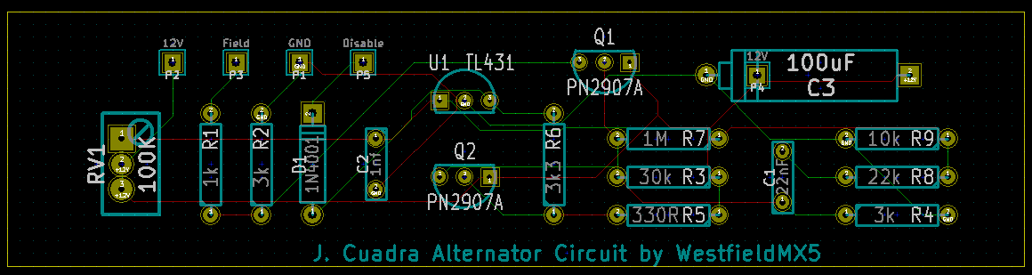
I added pad P4 so you can choose to install C3 upright or layed down (space concern).
To fine tune the voltage, I replaced the 48K7 resistor with a 100K trimmer. You should have a spare when you build the Megasquirt (but you can still use a resistor). .
I also added the 'disable' diode as discussed in the 'Disable alternator field' topic.
Supply Gnd, 12V and connect Field to the alternator. When you ground the Disable pin, the alternator stops charging. I use a gen purpose output to disable the alternator while I'm cranking (<700rpm).
I'll make the board 25*100mm so it can slide into the top slot of a standard Megasquirt case.
Having no MS at hand, can someone verify if 100mm would work? I believe a V3 pcb is 101.4mm (4"), but to keep costs down, I can only have them made at 100mm.
I wouldn't want them to fall out of the slots of course, so this needs to be verified..
Price shouldn't be over $10.
I prefer Jason's rock solid design over the software alternator control in the latest alpha's. I managed to blew the fuses of the MS3 Pro trying to get it to charge over 12.5V but below 20V
). I added pad P4 so you can choose to install C3 upright or layed down (space concern).
To fine tune the voltage, I replaced the 48K7 resistor with a 100K trimmer. You should have a spare when you build the Megasquirt (but you can still use a resistor). .
I also added the 'disable' diode as discussed in the 'Disable alternator field' topic.
Supply Gnd, 12V and connect Field to the alternator. When you ground the Disable pin, the alternator stops charging. I use a gen purpose output to disable the alternator while I'm cranking (<700rpm).
I'll make the board 25*100mm so it can slide into the top slot of a standard Megasquirt case.
Having no MS at hand, can someone verify if 100mm would work? I believe a V3 pcb is 101.4mm (4"), but to keep costs down, I can only have them made at 100mm.
I wouldn't want them to fall out of the slots of course, so this needs to be verified..
Price shouldn't be over $10.
Last edited by WestfieldMX5; 09-22-2013 at 09:57 AM.

Reply
 0
0

0
09-22-2013, 10:16 AM
#2

I'm interested in the collective knowledge here regarding the use of L9911 for alternator control. It seems a very simple commercially available solution.
http://www.st.com/web/en/resource/te...CD00046504.pdf
http://www.st.com/web/en/resource/te...CD00046504.pdf
Reply
0
0
 09-27-2013, 07:35 AM
#5
Boost Czar


iTrader: (62)
Join Date: May 2005
Location: Chantilly, VA
Posts: 79,490
Total Cats: 4,079
Does that 100K pot tune the voltage? I've been using all 1% resistors and every board I've but switches right at 14.2v, but I'd like to push it to 14.7v like the stock alt runs at.
sad you werent happy with the pwm alt control within ms3; I thought DIY had success with it.
sad you werent happy with the pwm alt control within ms3; I thought DIY had success with it.
Reply
0
0
09-27-2013, 03:00 PM
#6
Senior Member
Thread Starter
Join Date: Nov 2007
Location: Belgium
Posts: 999
Total Cats: 73
Yes, the pot is to finetune the voltage. I have mine around 14.5-14.6V.
No need to get 1% resistors and there's a spare pot from the opto circuit.
PWM alt control doesn't work at all on my car. I played with it for a while but it either didn't charge or charged over 20V (overload on the 20V setting on my DVM). When the fuse on my Pro finally blew, I decided to call it quits and build the circuit.
No matter what I did, I just couldn't get it right. For the little time it takes to build the circuit, I see no point in spending hours trying to get the pwm right. IIRC, even DIY didn't get it entirly correct (overshooting in some conditions etc). Jason's circuit is pretty much rock solid and with the diode we can disable it at will. Best of both worlds.
Reply
0
0

 10-31-2013, 09:01 PM
#10
Newb

Join Date: Dec 2009
Posts: 11
Total Cats: 2
Two boards here also.
I am running an AEM-EMS4 on a '00. Still not quite sure why all the posts about this connect 'Field' to pin 1O ( grey/red wire ), and not pin 1T ( grey wire ). From the wiring diagram it looks like 1O read the field output where 1T switches the transistor, which activates an internal relay. Could you explain this?
I am running an AEM-EMS4 on a '00. Still not quite sure why all the posts about this connect 'Field' to pin 1O ( grey/red wire ), and not pin 1T ( grey wire ). From the wiring diagram it looks like 1O read the field output where 1T switches the transistor, which activates an internal relay. Could you explain this?
Reply
0
0
11-01-2013, 11:24 AM
#11
Senior Member
Thread Starter
Join Date: Nov 2007
Location: Belgium
Posts: 999
Total Cats: 73
I didn't get any further with this but I'll look further into it.
Only having a MS3 Pro at my disposal, could somebody check if a 100mm board will fit in the slots of the MS2 / MS3 case without falling out?
Odd as it may seem, we definitely use 1O, not 1T. I've looked at the diagrams myself and all I can come up with is that the color codes are wrong or that I don't understand the workings of the alternator. The latter is more likely but who cares as long as it works
Last edited by WestfieldMX5; 11-01-2013 at 11:37 AM.
Reply
0
0
11-01-2013, 12:01 PM
#12
Boost Czar
iTrader: (62)
Join Date: May 2005
Location: Chantilly, VA
Posts: 79,490
Total Cats: 4,079
Remind me through constant PMs and Emails. I have a MS3x case handy.
I was actually using a standoff on the heatsink to mount mine, but that wouldn't work with the way to cut the case to mount the harness connector.
I was actually using a standoff on the heatsink to mount mine, but that wouldn't work with the way to cut the case to mount the harness connector.
Reply
0
0
11-01-2013, 07:50 PM
#13
Senior Member
Thread Starter
Join Date: Nov 2007
Location: Belgium
Posts: 999
Total Cats: 73
Yeah, that was the reason why I designed the board the way I did.
Once I know they fit, I'll have them made if I don't loose too much money on these.
The thing is that I've just decided to stop building MSses (MSs?), so I really no longer need the boards myself.
Shipment and import duties are stupid expensive :(.
Once I know they fit, I'll have them made if I don't loose too much money on these.
The thing is that I've just decided to stop building MSses (MSs?), so I really no longer need the boards myself.
Shipment and import duties are stupid expensive :(.
Reply
0
0
11-02-2013, 03:15 PM
#14
Boost Czar
iTrader: (62)
Join Date: May 2005
Location: Chantilly, VA
Posts: 79,490
Total Cats: 4,079
the boards are right around 100-101mm.
tab to tab it's about 97mm, so i think 100mm would be fine.
every time i think im done building MSes, people keep harassing me and i do them again.
tab to tab it's about 97mm, so i think 100mm would be fine.
every time i think im done building MSes, people keep harassing me and i do them again.
Reply
0
0
 11-03-2013, 10:06 AM
#17
Newb
Join Date: Dec 2009
Posts: 11
Total Cats: 2
I made the JC circuit last night. Man, I could write you 30K lines of clean C++, but put a soldering iron in my hands..it can get ugly. A couple of questions:
1) The other 'field' connection to the alternator ( 1T ) is that +12V, GND or just left disconnected?
2) Assuming said software guy has a power supply how do I bench test tis circuit?
1) The other 'field' connection to the alternator ( 1T ) is that +12V, GND or just left disconnected?
2) Assuming said software guy has a power supply how do I bench test tis circuit?
Reply
0
0
11-03-2013, 12:53 PM
#18
Senior Member
Thread Starter
Join Date: Nov 2007
Location: Belgium
Posts: 999
Total Cats: 73
1) Leave 1T disconnected
2) Easy if you have a lab power supply. Connect 12V power source to the 12V input of the circuit and measure the (output) voltage at the Field pin.
Raise the input voltage while keeping an eye on Field voltage. When the input is about 14.4V, the Field voltage should drop to (near) zero.
2) Easy if you have a lab power supply. Connect 12V power source to the 12V input of the circuit and measure the (output) voltage at the Field pin.
Raise the input voltage while keeping an eye on Field voltage. When the input is about 14.4V, the Field voltage should drop to (near) zero.
Reply
0
0
11-03-2013, 05:20 PM
#20
Boost Czar
iTrader: (62)
Join Date: May 2005
Location: Chantilly, VA
Posts: 79,490
Total Cats: 4,079
1) Leave 1T disconnected
2) Easy if you have a lab power supply. Connect 12V power source to the 12V input of the circuit and measure the (output) voltage at the Field pin.
Raise the input voltage while keeping an eye on Field voltage. When the input is about 14.4V, the Field voltage should drop to (near) zero.
2) Easy if you have a lab power supply. Connect 12V power source to the 12V input of the circuit and measure the (output) voltage at the Field pin.
Raise the input voltage while keeping an eye on Field voltage. When the input is about 14.4V, the Field voltage should drop to (near) zero.
When I do it it drops to like 3v or something; but at exactly 14.2v, it will drop.
Reply
0
0


