MEGAsquirt A place to collectively sort out this megasquirt gizmo

Interest in NB alternator circuit board?

Thread Tools
 
Search this Thread
 
Old 11-11-2013, 09:13 PM
  #21  
Newb
 
adamvs's Avatar
 
Join Date: Dec 2009
Posts: 11
Total Cats: 2
Default

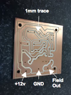
I needed to get this going to get my car running. With the help of Eagle software and their freeware offer, PCB to Gcode I was able to mill the PBC on a CNC mill I got a year and a half ago on CL.


I tested this out, the addition of the trim pot is brilliant! I used a 20 turn 1-100Kohm pot, you can dial the cutoff point pretty much wherever you want it. On bench test it's set to drop at 14.35V and it drops to effectively 0.


This works great. I'm stoked!
Attached Thumbnails Interest in NB alternator circuit board?-smallpcb.jpg   Interest in NB alternator circuit board?-finished-board.jpg  

Last edited by adamvs; 11-12-2013 at 11:21 AM. Reason: Text in the photo was incorrect
adamvs is offline  
Old 11-12-2013, 05:48 AM
  #22  
Senior Member
Thread Starter
 
WestfieldMX5's Avatar
 
Join Date: Nov 2007
Location: Belgium
Posts: 999
Total Cats: 73
Default

looks like you used a 100K trim pot (which is correct), not a 100 ohm.
BTW, measure the set point in the car as well. I found that it doesn't always give the same results in the car.
WestfieldMX5 is offline  
Old 11-12-2013, 11:24 AM
  #23  
Newb
 
adamvs's Avatar
 
Join Date: Dec 2009
Posts: 11
Total Cats: 2
Default

Originally Posted by WestfieldMX5
looks like you used a 100K trim pot (which is correct), not a 100 ohm.
Whoops, I dashed off that post last night in a big hurry. I just corrected the photo, if anyone looks this up in the future.
adamvs is offline  
Old 11-12-2013, 11:40 AM
  #24  
Boost Czar
iTrader: (62)
 
Braineack's Avatar
 
Join Date: May 2005
Location: Chantilly, VA
Posts: 79,493
Total Cats: 4,080
Default

now I want to post mine! but I don't have the pictures handy at the moment.
Braineack is offline  
Old 11-14-2013, 11:01 AM
  #25  
Newb
 
adamvs's Avatar
 
Join Date: Dec 2009
Posts: 11
Total Cats: 2
Default

Frank, what's the 'disable' pin and the diode all about?
adamvs is offline  
Old 11-14-2013, 11:17 AM
  #26  
Boost Czar
iTrader: (62)
 
Braineack's Avatar
 
Join Date: May 2005
Location: Chantilly, VA
Posts: 79,493
Total Cats: 4,080
Default

to be able to deactivate the circuit below a certain rpm. typically 300 so it's not trying to chrage during cranking.
Braineack is offline  
Old 11-15-2013, 10:27 PM
  #27  
Newb
 
adamvs's Avatar
 
Join Date: Dec 2009
Posts: 11
Total Cats: 2
Default

Originally Posted by Braineack
to be able to deactivate the circuit below a certain rpm. typically 300 so it's not trying to chrage during cranking.
OK, where does it fit into the circuit, ie, what does the diode connect to? It's hard to tell from WestfieldMX5's post.
adamvs is offline  
Old 11-16-2013, 06:01 AM
  #28  
Senior Member
Thread Starter
 
WestfieldMX5's Avatar
 
Join Date: Nov 2007
Location: Belgium
Posts: 999
Total Cats: 73
Default

banded side = ground to disable
other side goes to pin 3 of the TL431 (cathode)
WestfieldMX5 is offline  
Old 12-11-2013, 10:11 AM
  #29  
Newb
 
Muksimp's Avatar
 
Join Date: Jan 2013
Location: Finland
Posts: 23
Total Cats: 0
Default

WestfieldMX5, did you manage to get the boards into production? i would probably be interested in one, seems like i'm not getting mine build on the proto-area to work.
DIYPNP and -99 10AE
Muksimp is offline  
Old 12-11-2013, 01:24 PM
  #30  
Senior Member
Thread Starter
 
WestfieldMX5's Avatar
 
Join Date: Nov 2007
Location: Belgium
Posts: 999
Total Cats: 73
Default

Actually, I just sent the design out to have them produced. I have no clue how long it will take but I'll update here once they arrive.
I'm having 40 boards made
WestfieldMX5 is offline  
Old 12-13-2013, 09:52 PM
  #31  
Junior Member
iTrader: (2)
 
reddragon128's Avatar
 
Join Date: Jan 2012
Location: Norcal
Posts: 129
Total Cats: 0
Default

I want one!
reddragon128 is offline  
Old 01-07-2014, 05:01 PM
  #32  
Newb
 
kolcak's Avatar
 
Join Date: Jan 2014
Posts: 1
Total Cats: 0
Default

@WestfieldMX5, Thank you for the circuit, there is a need of trimming and alignment for the circuit but this is certainly worth my time. One thing however, whenever you’re charging batteries, one should always make sure that the power source being utilized is constant current source and the voltage has to be carefully adjusted so that the battery being charged doesn’t draw more current than the ratings. I believe that was the issue which has been addressed but there is also a need to avoid such issues altogether by a bit of care. The circuit for the alternator is all good. Reverse protection between power and ground will be a plus in this circuit which I’ll try to edit and upload.

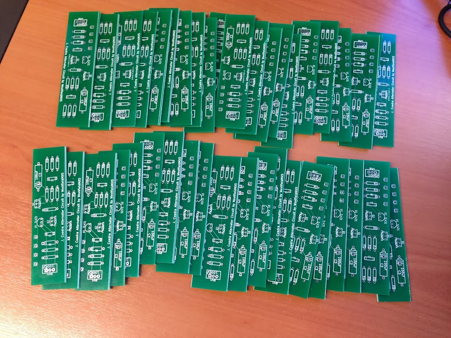
printed circuit board

Last edited by kolcak; 01-13-2014 at 12:12 PM.
kolcak is offline  
Old 01-27-2014, 01:05 PM
  #33  
Senior Member
Thread Starter
 
WestfieldMX5's Avatar
 
Join Date: Nov 2007
Location: Belgium
Posts: 999
Total Cats: 73
Default

Well, it's taken some time, but the boards have finally arrived. Will try to test one out tonight.


Attached Thumbnails Interest in NB alternator circuit board?-2014-01-31%25252009.21.02.jpg  

Last edited by WestfieldMX5; 01-31-2014 at 06:25 AM.
WestfieldMX5 is offline  
Old 01-27-2014, 08:22 PM
  #34  
Newb
 
adamvs's Avatar
 
Join Date: Dec 2009
Posts: 11
Total Cats: 2
Default

They look great. I'm in for two. I'll PM you.

Edit: well, looks like I don't have enough posts to PM you. PM me.

Last edited by adamvs; 01-27-2014 at 08:28 PM. Reason: change PM details
adamvs is offline  
Old 01-28-2014, 12:27 AM
  #35  
Newb
 
Muksimp's Avatar
 
Join Date: Jan 2013
Location: Finland
Posts: 23
Total Cats: 0
Default

Great. Please PM me with your e-mail, i'll take one.
Muksimp is offline  
Old 01-28-2014, 07:50 AM
  #36  
Boost Czar
iTrader: (62)
 
Braineack's Avatar
 
Join Date: May 2005
Location: Chantilly, VA
Posts: 79,493
Total Cats: 4,080
Default

clever way to print, they cut easily?
Braineack is offline  
Old 01-28-2014, 08:11 AM
  #37  
Senior Member
Thread Starter
 
WestfieldMX5's Avatar
 
Join Date: Nov 2007
Location: Belgium
Posts: 999
Total Cats: 73
Default

haven't tried yet. They wouldn't let me use rows with lots of holes. If needed I'll use the table saw
WestfieldMX5 is offline  
Old 01-29-2014, 11:34 AM
  #38  
Senior Member
Thread Starter
 
WestfieldMX5's Avatar
 
Join Date: Nov 2007
Location: Belgium
Posts: 999
Total Cats: 73
Default

Tested and working fine.

Price for a bare board is $12 each + $4 shipping up to 4 boards
In europe: 9 euro each and 2 euro shipping up to 4 boards.


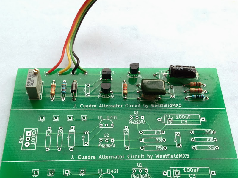
Yes, there's a capacitor missing

Attached Thumbnails Interest in NB alternator circuit board?-2014-01-29%25252016.52.06.jpg  

Last edited by WestfieldMX5; 02-01-2014 at 08:32 AM.
WestfieldMX5 is offline  
Old 01-29-2014, 11:37 AM
  #39  
Newb
 
Muksimp's Avatar
 
Join Date: Jan 2013
Location: Finland
Posts: 23
Total Cats: 0
Default

I'll take one, Euro.

Please PM me your details, or e-mail me at Maksim@Petrov.fi
Muksimp is offline  
Old 01-29-2014, 11:53 AM
  #40  
Boost Czar
iTrader: (62)
 
Braineack's Avatar
 
Join Date: May 2005
Location: Chantilly, VA
Posts: 79,493
Total Cats: 4,080
Default

your video cuts out before we can see what voltage the output goes to ground at.
Braineack is offline  


Quick Reply: Interest in NB alternator circuit board?


All times are GMT -4. The time now is 09:43 PM.