Joe's revised Spark Out vs. MSExtra Manual - TC4427 Spark Output
 02-26-2015, 06:04 PM
#21
Junior Member

Join Date: Feb 2015
Location: Texas
Posts: 53
Total Cats: -63
do i need jumper D1 and D2 on this set up Megasquirt 2 Assembly - Miata Turbo FAQ ??
and what is that last black wire for coming of JS7 ??
and he talk about "quot" Also, JS0 to JS4 will not work at input/outputs unless you jump s12c to JS9. So jump s12c to JS9. ?? dose not tell you what JS0 and JS4 are for .
and Braineack on your set up you say look at the pic and they are all gone . Can you fix them ??

Reply
 0
0

0
02-26-2015, 07:40 PM
#22
Junior Member
Thread Starter
iTrader: (1)

Join Date: Aug 2014
Location: Wisconsin
Posts: 78
Total Cats: 12
I followed the instructions on MSExtra pg.76 Ch. 5.3.1.3
Parts required for two channels:
TC4427AEPA
2x 15R 1/8W resistors
Wire it up just like the picture.
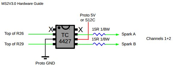
I put all the devices through the holes and solder bridged them.
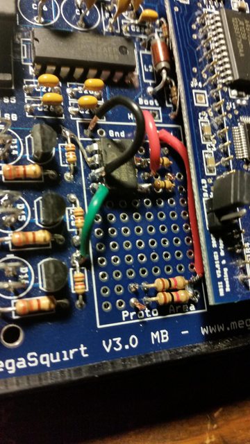
On the underside, I ran wires to IGN and IAC2B for the signal out to the coils. (Black and Green wires)
Lastly, make sure to change your ignition setup in TunerStudio
Ignition Settings > Ignition Options > Spark Output = Going Low
This setup should work just like "Joe Perez's Better Spark Out Circuit."
The two LEDs that your ignition runs off of (D14 & D16) will stay lit and flick off when it sends the signal to the ignition coil. Just a reminder, testing with a JimStim is cheaper and easier than replacing a coil if you are unsure (I know I was).
A cool thing is if you want to do COP Sequential Ignition (4 channels), you get the same components and replicate. I plan on going this route in the future and it shouldn't be very difficult to do since I've done it once already.
Thank you Braineack, Ben, Ted75zcar, Matt Cramer for your help on this.
Parts required for two channels:
TC4427AEPA
2x 15R 1/8W resistors
Wire it up just like the picture.
I put all the devices through the holes and solder bridged them.
On the underside, I ran wires to IGN and IAC2B for the signal out to the coils. (Black and Green wires)
Lastly, make sure to change your ignition setup in TunerStudio
Ignition Settings > Ignition Options > Spark Output = Going Low
This setup should work just like "Joe Perez's Better Spark Out Circuit."
The two LEDs that your ignition runs off of (D14 & D16) will stay lit and flick off when it sends the signal to the ignition coil. Just a reminder, testing with a JimStim is cheaper and easier than replacing a coil if you are unsure (I know I was).
A cool thing is if you want to do COP Sequential Ignition (4 channels), you get the same components and replicate. I plan on going this route in the future and it shouldn't be very difficult to do since I've done it once already.
Thank you Braineack, Ben, Ted75zcar, Matt Cramer for your help on this.
Reply
0
0
02-27-2015, 05:59 PM
#25
Boost Czar


iTrader: (62)
Join Date: May 2005
Location: Chantilly, VA
Posts: 79,493
Total Cats: 4,080
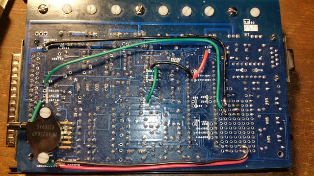
your spark output looks good, but the crank cam input looks funky to me.
Was the goal to run the crank signal to the OPTO circuit and the cam signal through the VR circuit?
how exactly is VRIN and OPTOIN wired? I see they go to the proto and then 1K resistors, then nowhere.
If that was the intention, I can show you how to wire it, but as is it looks like youre combining them into both circuits.
Reply
0
0
03-01-2015, 10:54 PM
#26
Junior Member
Thread Starter
iTrader: (1)
Join Date: Aug 2014
Location: Wisconsin
Posts: 78
Total Cats: 12
Braineack,
the Proto feeds 5v to the CKP and CMP sensors following MSExtra and this thread:
https://www.miataturbo.net/megasquir...6/#post1184085
I've put an O Scope (cheap one) on and get signals from the JimStim, but super faint (about 1v). I feel like the pullups don't play nice with the JimStim.
These signals look to be my last obstacle to getting this fully functional so I'm excited to sort them out.
Reply
0
0
03-05-2015, 09:40 AM
#27
Boost Czar
iTrader: (62)
Join Date: May 2005
Location: Chantilly, VA
Posts: 79,493
Total Cats: 4,080
bad answer. i said how exactly. from what i can tell you combined both cmk and cmp into one circuit.
notice how your inputs look nothing like mine in that picture?
ill walk you through this when i have more time later today.
but you should mimic my green, red, and purple wires. the yellow are the spark.
notice how your inputs look nothing like mine in that picture?
ill walk you through this when i have more time later today.
but you should mimic my green, red, and purple wires. the yellow are the spark.
Reply
0
0
03-05-2015, 01:53 PM
#28
Junior Member
Thread Starter
iTrader: (1)
Join Date: Aug 2014
Location: Wisconsin
Posts: 78
Total Cats: 12
Hi Braineack,
I used these instructions to set up for the cam sensor
5.2.3
a) Solder a link between VRIN and TACHSELECT
b) Solder a wire between VrOUTInv and TSEL
c) Install a 1k resistor (any value 470R - 2k2 is likely OK) in the proto area. Connect one end to the 5V hole and
join the other end to VRIN with a jumper wire.
d) With a small screwdriver, turn the pots, R52 and R56, about 12 turns anticlockwise (sometimes you may feel
a "click" when the end position is reached, they can't be damaged by turning too far.) and then turn R56 back
about 6 turns clockwise.
5.2.14.2 Adding a cam sensor input - hall sensor / optical sensor
This option uses the spare opto-isolator on the mainboard for the cam input and matches the polarity inversion
of the VR/universal tach input.
This section is for open-collector sensors as covered in 5.2.3 that ground switch only.
a) The OptoIn pad should be connected to a spare pin on the main DB37 connector (e.g. SPR3)
b) Connect OptoOut to JS10 (ensuring that nothing else is connected.)
c) Jumper XG1 - XG2
d) Check that R12 is a 390R to 470R resistor, replace if not.
e) Install a 470R 1/4W resistor on the proto area to +5V.
f) Jumper the other end of the 470R resistor to OptoIn (joining the jumper wire there.)
g) Ensure that C30 is not fitted.
I followed your instructions to use VROutInv instead of VROut.
I'm inclined to just copy your pic at this point unless the current setup just needs a little tweaking.
Reply
0
0
03-05-2015, 04:00 PM
#29
Boost Czar
iTrader: (62)
Join Date: May 2005
Location: Chantilly, VA
Posts: 79,493
Total Cats: 4,080
I think you're close looking again, but this is exactly what I'd do:
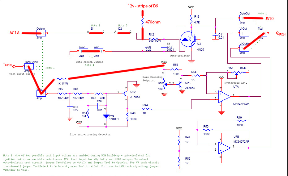
I think the only issue with yours is that you need to bring a 12v pullup to optoin, not 5v.
then i cant for the love of me remember if you really need to use VROUTIV or just straight up VROUT to TSEL. But a composite log will quickly figure that out.
I think the only issue with yours is that you need to bring a 12v pullup to optoin, not 5v.
then i cant for the love of me remember if you really need to use VROUTIV or just straight up VROUT to TSEL. But a composite log will quickly figure that out.
Reply
0
0
03-06-2015, 11:05 AM
#30
Supporting Vendor

iTrader: (33)
Join Date: Jul 2006
Location: atlanta-ish
Posts: 12,659
Total Cats: 134
Hi Braineack,
I used these instructions to set up for the cam sensor
5.2.3
a) Solder a link between VRIN and TACHSELECT
b) Solder a wire between VrOUTInv and TSEL
c) Install a 1k resistor (any value 470R - 2k2 is likely OK) in the proto area. Connect one end to the 5V hole and
join the other end to VRIN with a jumper wire.
d) With a small screwdriver, turn the pots, R52 and R56, about 12 turns anticlockwise (sometimes you may feel
a "click" when the end position is reached, they can't be damaged by turning too far.) and then turn R56 back
about 6 turns clockwise.
5.2.14.2 Adding a cam sensor input - hall sensor / optical sensor
This option uses the spare opto-isolator on the mainboard for the cam input and matches the polarity inversion
of the VR/universal tach input.
This section is for open-collector sensors as covered in 5.2.3 that ground switch only.
a) The OptoIn pad should be connected to a spare pin on the main DB37 connector (e.g. SPR3)
b) Connect OptoOut to JS10 (ensuring that nothing else is connected.)
c) Jumper XG1 - XG2
d) Check that R12 is a 390R to 470R resistor, replace if not.
e) Install a 470R 1/4W resistor on the proto area to +5V.
f) Jumper the other end of the 470R resistor to OptoIn (joining the jumper wire there.)
g) Ensure that C30 is not fitted.
I followed your instructions to use VROutInv instead of VROut.
I'm inclined to just copy your pic at this point unless the current setup just needs a little tweaking.
I used these instructions to set up for the cam sensor
5.2.3
a) Solder a link between VRIN and TACHSELECT
b) Solder a wire between VrOUTInv and TSEL
c) Install a 1k resistor (any value 470R - 2k2 is likely OK) in the proto area. Connect one end to the 5V hole and
join the other end to VRIN with a jumper wire.
d) With a small screwdriver, turn the pots, R52 and R56, about 12 turns anticlockwise (sometimes you may feel
a "click" when the end position is reached, they can't be damaged by turning too far.) and then turn R56 back
about 6 turns clockwise.
5.2.14.2 Adding a cam sensor input - hall sensor / optical sensor
This option uses the spare opto-isolator on the mainboard for the cam input and matches the polarity inversion
of the VR/universal tach input.
This section is for open-collector sensors as covered in 5.2.3 that ground switch only.
a) The OptoIn pad should be connected to a spare pin on the main DB37 connector (e.g. SPR3)
b) Connect OptoOut to JS10 (ensuring that nothing else is connected.)
c) Jumper XG1 - XG2
d) Check that R12 is a 390R to 470R resistor, replace if not.
e) Install a 470R 1/4W resistor on the proto area to +5V.
f) Jumper the other end of the 470R resistor to OptoIn (joining the jumper wire there.)
g) Ensure that C30 is not fitted.
I followed your instructions to use VROutInv instead of VROut.
I'm inclined to just copy your pic at this point unless the current setup just needs a little tweaking.

Reply
0
0

Thread
Thread Starter
Forum
Replies
Last Post
Zaphod
MEGAsquirt
47
10-26-2018 11:00 PM


