MS1V3 Wiring harness horrors
 04-05-2013, 06:28 PM
#1
Junior Member

Thread Starter
iTrader: (2)

Join Date: Jul 2011
Location: Houston, Tx
Posts: 167
Total Cats: 4
Today I received a used Brain-built MS1V3 from a forum member here. Somewhere along the line, one of the previous owners of the unit absolutely mangled the 64-pin connector side of the harness. Everything appears to be connected, they are just poorly soldered and the joints are exposed. I have purchased a new 64-pin connector and I am now in the process of soldering everything to the new connector and confirming a few things.
First off, the DB37 connector appears to be untouched and looks exactly like the DB37 from Braineack's DIY thread:
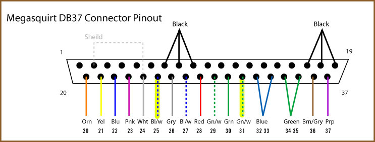
The first thing that concerns me is the ground wires on the 64-pin connector. The previous owner has one thick black wire connected to 2C and another thick black wire connected to 2A. 2D and 2B were left untouched. (Note that one of the black wires is connected to pins 7,8,9 and the other is connected to pins 17,18,19 on the DB37 connector, just like in the picture above.) Is this something I need to fix? According to Braineack's DIY thread, one wire should be split between 2C,2D and the other split between 2A,2B:
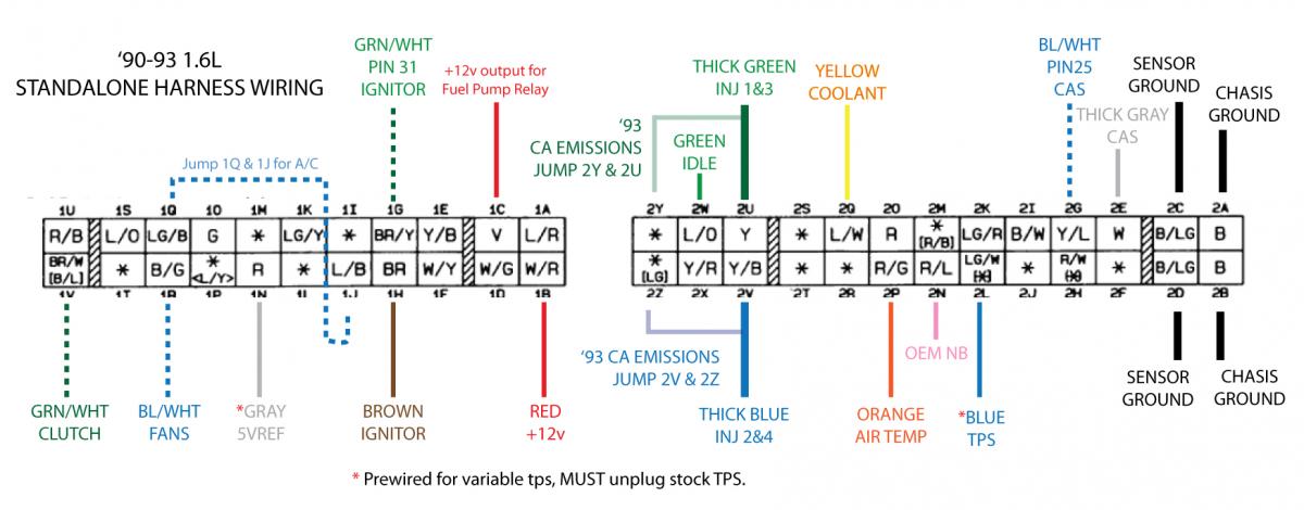
Second, on my 64-pin connector, the wires connected to 1G and 1H are opposite of the picture above. I have a brown wire going into 1G and a GRN/WHT wire going into 1H. Is this something that was done to some of the units, or did the previous owner just mess up when soldering everything back to the connector?
Any input would be greatly appreciated!
First off, the DB37 connector appears to be untouched and looks exactly like the DB37 from Braineack's DIY thread:
The first thing that concerns me is the ground wires on the 64-pin connector. The previous owner has one thick black wire connected to 2C and another thick black wire connected to 2A. 2D and 2B were left untouched. (Note that one of the black wires is connected to pins 7,8,9 and the other is connected to pins 17,18,19 on the DB37 connector, just like in the picture above.) Is this something I need to fix? According to Braineack's DIY thread, one wire should be split between 2C,2D and the other split between 2A,2B:
Second, on my 64-pin connector, the wires connected to 1G and 1H are opposite of the picture above. I have a brown wire going into 1G and a GRN/WHT wire going into 1H. Is this something that was done to some of the units, or did the previous owner just mess up when soldering everything back to the connector?
Any input would be greatly appreciated!

Reply
 0
0

0
04-06-2013, 01:56 PM
#2
Boost Czar

iTrader: (62)
Join Date: May 2005
Location: Chantilly, VA
Posts: 79,490
Total Cats: 4,079
That diagram is probably for a MS2, so leave the brown and g/w wire as installed on the harness; reverse from the picture.
grounds on the DB37 are: 1-2 and 7-19
I personally like to wire pins 1 and 2 to 4C and 4B, then two each on any other the others to 4A and 4B. Not using a big fat wires, so it would be 6 18g wires; if that makes sense.
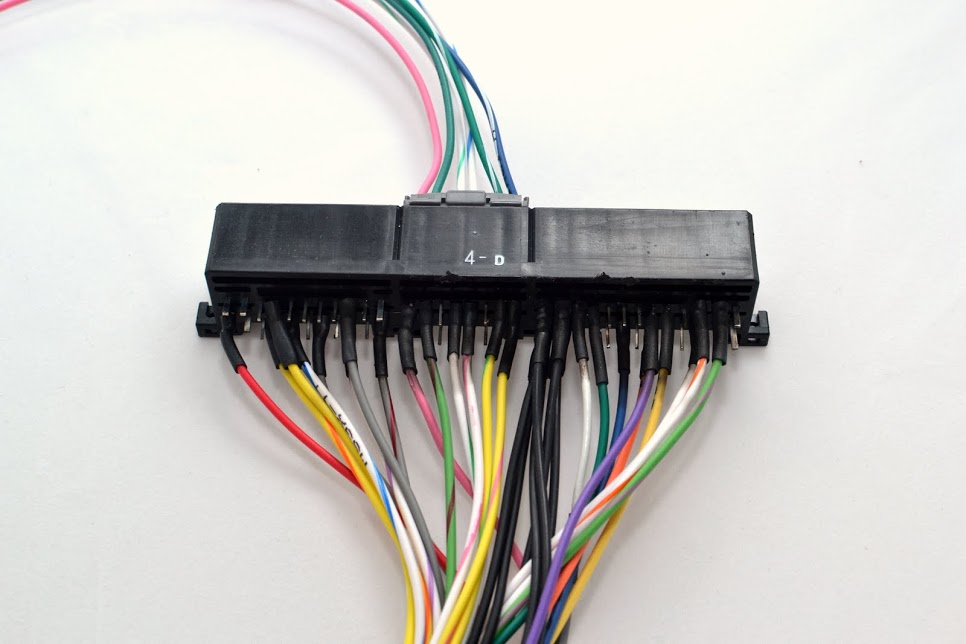
Take caution when soldering the 64 pin, get a tab of solder on the pins and wires before merging them. use heatshrink wrap, then when you're finished coat it all in hot glue to really hold and support the wires to protect them from stress and vibrations so the they dont break off at the solder joint or pull out of the connector itself.
aim for this:
then:
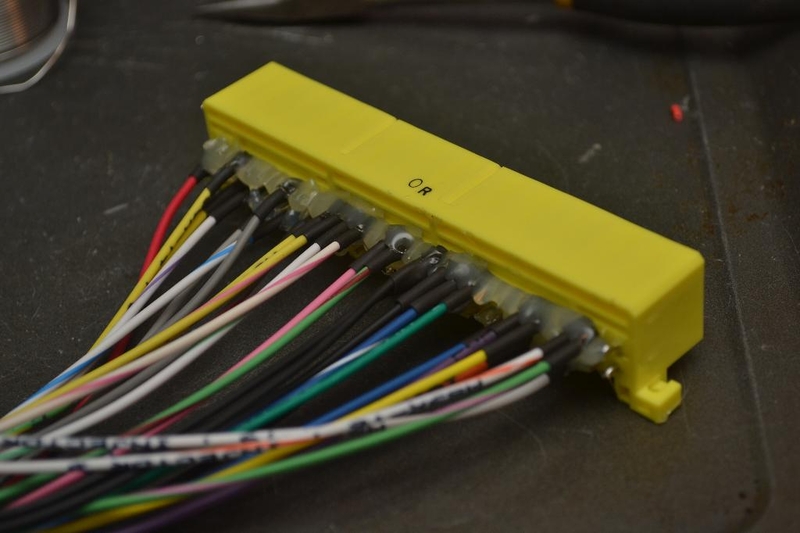
I ran out of glue here, but build it up to like a full inch or so.

Also I take great care in wiring the wires in order so they all line up pretty and nice.
grounds on the DB37 are: 1-2 and 7-19
I personally like to wire pins 1 and 2 to 4C and 4B, then two each on any other the others to 4A and 4B. Not using a big fat wires, so it would be 6 18g wires; if that makes sense.
Take caution when soldering the 64 pin, get a tab of solder on the pins and wires before merging them. use heatshrink wrap, then when you're finished coat it all in hot glue to really hold and support the wires to protect them from stress and vibrations so the they dont break off at the solder joint or pull out of the connector itself.
aim for this:
then:
I ran out of glue here, but build it up to like a full inch or so.
Also I take great care in wiring the wires in order so they all line up pretty and nice.
Reply
0
0
04-06-2013, 03:25 PM
#3
Junior Member
Thread Starter
iTrader: (2)
Join Date: Jul 2011
Location: Houston, Tx
Posts: 167
Total Cats: 4
Brain,
Did you mean pins 1 and 2 to 2C and 2D, respectively (2C and 2D being the two pins labeled 'SENSOR GROUND' in the diagram)? And then any two of pins 7-19 wired to 2A and 2B? Don't think I'm following where the 6 18g wires come from.
Did you mean pins 1 and 2 to 2C and 2D, respectively (2C and 2D being the two pins labeled 'SENSOR GROUND' in the diagram)? And then any two of pins 7-19 wired to 2A and 2B? Don't think I'm following where the 6 18g wires come from.
Reply
0
0

Thread
Thread Starter
Forum
Replies
Last Post
Zaphod
MEGAsquirt
47
10-26-2018 11:00 PM


