Megasquirt on a 99 (work safe again.)
 07-25-2008, 08:35 PM
#81
Junior Member
Thread Starter
iTrader: (3)

Join Date: Mar 2008
Location: Sunnyvale, ca
Posts: 220
Total Cats: 0
Any help guys? i would appreciate it greatly!
A picture to help with the helping..
also, looks like i found a place to get the stock other end of my db37 adapter... i am not sure if this is it, but i found it in cjernigan;s post from a long time ago...
http://www.onlinecomponents.com/buy/AMP-TYCO/1745187/.
is this ok? will this be all i need since i believe i have everything else... the wires and the db37?
thanks alot!
Last edited by Serper3; 07-25-2008 at 08:51 PM.

Reply
 0
0

0
07-26-2008, 11:38 PM
#83
Junior Member
Thread Starter
iTrader: (3)
Join Date: Mar 2008
Location: Sunnyvale, ca
Posts: 220
Total Cats: 0
Joe? Abe? anyone lol? if someone would like to just finish the build for me i would be most obliged! (i would deffinately compensate). if not, some help for me to figure out all these circuits and how they are built and i would promise to do a write up once i am done with my build!
thanks again guys!
thanks again guys!
Reply
0
0
07-27-2008, 07:52 PM
#84
figuring out which of those componants you left off you don't need means going through the schematic, item by item, searching, figuring out what circuit they go to, if they effect anything else, etc etc etc. It'll take a while and I've got precious little motivaiton to do it.
The half-moon thing is very likely the transistor. Black things? I'm not sure, if they have a stripe they are likely diodes.
Jumper wire and white wire are the same thing. Any wire you have that fits in the holes will do.
the spark outputs you'll want to do per braineak's write up. I put my resistors on the top side of the board which I think looks cleaner but it doesn't change anything electrically, just do what's more comfortable for you. But remember the spark input wants to use the radioshack dual op-amp, not the NA miata inputs B. likely put.
You should be able to test some stuff with the stim to see if it's working. But I'd say you ought to go through the schematic and figure out what all the stuff you left off is.
Reply
0
0
07-28-2008, 04:16 PM
#85
Junior Member
Thread Starter
iTrader: (3)
Join Date: Mar 2008
Location: Sunnyvale, ca
Posts: 220
Total Cats: 0
after much debating and considering of alternatives, i think i am just going to do an ms1 parallel install. i talked to badboy8800 who is running this setup and it seems like with my limited electrical knowledge this would be an easier build for me.
so far it looks like this is what i need to do:
1. order ms1 chip from diyautotune.
2. order a boomslang from them. i am not sure though wich one i need can someone please kind enough to link me the harness i would need to run parallel.
3. i am also going to have to obviously finish building the ms. since i am doing the parallel ms1 i need to build it exactly like in braineaks thread wich should be easier than trying to go through the megamanual and trying to figure out what i need or dont.
4. i need a cas from a 95-97 car.
again thanks alot for your help guys i appreciate it immensly. i just hope that this way, i can get my car running sooner with less issues and with out you guys holding my hand so much!
Thanks again!
Henry.
Reply
0
0
07-28-2008, 05:06 PM
#86
Your funeral.
Seriously, what are you actually missing? You should really get a jimstim, and you'll have the whole thing figured out in like 20 minutes. You stick it on there, and you'll know if the fans and all that are working. What are your real questions?
BTW - all that "what do I leave off the board" stuff is going to be the same whether you have the bad timing of a CAS or not. Those are not MS-II specific mods.
The *easy* answer: Build everything. You could ahve been done with this weeks ago if you'd just done that. You're giving up on the optimal solution because you can't optimize it?
Reply
0
0
07-28-2008, 05:57 PM
#87

Your funeral.
Seriously, what are you actually missing? You should really get a jimstim, and you'll have the whole thing figured out in like 20 minutes. You stick it on there, and you'll know if the fans and all that are working. What are your real questions?
BTW - all that "what do I leave off the board" stuff is going to be the same whether you have the bad timing of a CAS or not. Those are not MS-II specific mods.
The *easy* answer: Build everything. You could ahve been done with this weeks ago if you'd just done that. You're giving up on the optimal solution because you can't optimize it?
Seriously, what are you actually missing? You should really get a jimstim, and you'll have the whole thing figured out in like 20 minutes. You stick it on there, and you'll know if the fans and all that are working. What are your real questions?
BTW - all that "what do I leave off the board" stuff is going to be the same whether you have the bad timing of a CAS or not. Those are not MS-II specific mods.
The *easy* answer: Build everything. You could ahve been done with this weeks ago if you'd just done that. You're giving up on the optimal solution because you can't optimize it?
I just have to figure out the schematics that Abe created for the MSII standalone in comparison to the ones that they posted on the MSII manual.
Reply
0
0
07-28-2008, 06:14 PM
#88
The MS-II ones in the manual are just plain wrong. They were based on misinformation, not knowing the type of sensor which is used.
You can do the simpler transistor input (or even just a pull up resistor) but the nice part about the op-amp based input is it acts like a strongly filtered input, but doesn't have all the nasty analog aspects. Basically, the circuit ignores ANY signal shorter than the propagation delay of the op-amp. If you do something similar with caps, you can get a variable timing out of it. This will have a fixed delay. It's not only a very classic, textbook design, I copied it 1:1 from the OEM inputs. It's what the '99 sensors were designed to work with!
All I did was leave out the caps on my build since I haven't had noise issues and it gives me SLIGHTLY more repeatable timing.

Er, obviously there's no pin 43 and 44, I don't recall off the top of my head what they should be, but it's the same any other circuit would have used. When someone figured this out let me know I'll update the picture. :-) I could look it up later but I'm swamped at work right now and haven't the time.
edit: Well, the CRK is definately pin 14. That's half the battle right there.
You can do the simpler transistor input (or even just a pull up resistor) but the nice part about the op-amp based input is it acts like a strongly filtered input, but doesn't have all the nasty analog aspects. Basically, the circuit ignores ANY signal shorter than the propagation delay of the op-amp. If you do something similar with caps, you can get a variable timing out of it. This will have a fixed delay. It's not only a very classic, textbook design, I copied it 1:1 from the OEM inputs. It's what the '99 sensors were designed to work with!
All I did was leave out the caps on my build since I haven't had noise issues and it gives me SLIGHTLY more repeatable timing.
Er, obviously there's no pin 43 and 44, I don't recall off the top of my head what they should be, but it's the same any other circuit would have used. When someone figured this out let me know I'll update the picture. :-) I could look it up later but I'm swamped at work right now and haven't the time.
edit: Well, the CRK is definately pin 14. That's half the battle right there.
Reply
0
0
07-28-2008, 06:27 PM
#89
Boost Pope


iTrader: (8)
Join Date: Sep 2005
Location: Chicago. (The less-murder part.)
Posts: 33,017
Total Cats: 6,587
For both MS1 and MS2, the crank signal goes to the Tsel pad, which brings it to pin 14 of U1. On MS1, this is the hardware interrupt, on MS2 it's just a general purpose input.
For MS1, the cam signal goes to JS8, which takes it to pin 11 of U1.
For MS2, the cam signal goes to JS10, which takes it to pin 17 of U1.
For MS1, the cam signal goes to JS8, which takes it to pin 11 of U1.
For MS2, the cam signal goes to JS10, which takes it to pin 17 of U1.
Reply
0
0
07-28-2008, 07:37 PM
#90
^^ that just made it easier to understand. thanks.
SO basically to convert over to MSII you keep the DB harness the same, but just splice into the stock cam and crank sensors, respectively. Then i would then build the circuits for the inputs (if running in parallel, using Arga's circuit; using Abe's circuit for standalone), but you need to get rid of the miata mods for the MSI correct? Are the spark outputs and mods on the board kept the same?
I think im beginning to understand all this stuff now the more that i look at it. Im off to frys to get the stuff i need ^_^
If i recall correctly, arga's input circuits for the NB require the use of transistors rather than OP amps? i gotta find the picture of it.
EDIT: found it

EDIT2: i found this cleaned up version of your circuits Abe, but i think you should change that input to JS8 as it should be going to JS10

SO basically to convert over to MSII you keep the DB harness the same, but just splice into the stock cam and crank sensors, respectively. Then i would then build the circuits for the inputs (if running in parallel, using Arga's circuit; using Abe's circuit for standalone), but you need to get rid of the miata mods for the MSI correct? Are the spark outputs and mods on the board kept the same?
I think im beginning to understand all this stuff now the more that i look at it. Im off to frys to get the stuff i need ^_^
If i recall correctly, arga's input circuits for the NB require the use of transistors rather than OP amps? i gotta find the picture of it.
EDIT: found it
EDIT2: i found this cleaned up version of your circuits Abe, but i think you should change that input to JS8 as it should be going to JS10
Last edited by Marc D; 07-28-2008 at 07:49 PM.
Reply
0
0
07-28-2008, 08:42 PM
#91
Junior Member
Thread Starter
iTrader: (3)
Join Date: Mar 2008
Location: Sunnyvale, ca
Posts: 220
Total Cats: 0
I guess I am just going to build the ms completely.. I want to go standalone but I feel so incompetent with my reading of diagrams. I am also not sure where these components from the schematic you guys drew are to go. Proto area? Seperate board? And the miata mods also vary from braineaks sticky?
Thanks for the help guys! I must admit this is more challenging than I though!
Thanks for the help guys! I must admit this is more challenging than I though!
Reply
0
0
07-28-2008, 09:02 PM
#92
Boost Pope
iTrader: (8)
Join Date: Sep 2005
Location: Chicago. (The less-murder part.)
Posts: 33,017
Total Cats: 6,587
Yes!
Also yes!
Well, you probably are incompetent just at the moment. Life kinda sucks that way. Once you're totally done and it's running, then you'll be competent. "Youth is wasted on the young" and competence is wasted on those who are done building their Megasquirts.
The components in the last couple of schematics posted are ones you have to add. Usually in the proto area, though you can build them on a seperate board. My last ignition trigger input circuit (the one I'm currently using) is in a whole separate box external from the MS!
The ignition outputs will be the same. With the inputs, well, there's about ten different ways to build them and no single consensus on which is best. For NB sensors, Abe's circuit is proven reliable. For NA sensors, either the braineack/DIY circuit or These Circuits (my personal preference) should also work. In my case, none of them worked, so I trashed my CAS and built a VR wheel.
Remember the old saying- that which does not kill you may still leave you paralyzed and on a respirator, dependent on others to change your colostomy bag. 
I want to go standalone
but I feel so incompetent with my reading of diagrams. I am also not sure where these components from the schematic you guys drew are to go. Proto area? Seperate board?
The components in the last couple of schematics posted are ones you have to add. Usually in the proto area, though you can build them on a seperate board. My last ignition trigger input circuit (the one I'm currently using) is in a whole separate box external from the MS!
And the miata mods also vary from braineaks sticky?
Thanks for the help guys! I must admit this is more challenging than I though!
Reply
0
0
07-28-2008, 09:09 PM
#93
Boost Pope
iTrader: (8)
Join Date: Sep 2005
Location: Chicago. (The less-murder part.)
Posts: 33,017
Total Cats: 6,587
SO basically to convert over to MSII you keep the DB harness the same, but just splice into the stock cam and crank sensors, respectively. Then i would then build the circuits for the inputs (if running in parallel, using Arga's circuit; using Abe's circuit for standalone),
but you need to get rid of the miata mods for the MSI correct? Are the spark outputs and mods on the board kept the same?
EDIT2: i found this cleaned up version of your circuits Abe, but i think you should change that input to JS8 as it should be going to JS10
Reply
0
0
07-28-2008, 10:00 PM
#94
Junior Member
Thread Starter
iTrader: (3)
Join Date: Mar 2008
Location: Sunnyvale, ca
Posts: 220
Total Cats: 0
So are you referring to the drawings in post 91? Do I build them identically to how they are drawn? Do I have to do any other miata specific mods like in braineaks thread? I am assuming at least the fan mod like in braineaks thread? This seems like too little stuff to do..
Reply
0
0
07-28-2008, 10:19 PM
#95
Boost Pope
iTrader: (8)
Join Date: Sep 2005
Location: Chicago. (The less-murder part.)
Posts: 33,017
Total Cats: 6,587
The drawings in post 91 are specific to the use of NB Miata crank and cam sensors on a MS1 or MS2.
You must still do all the other mods- spark out, fan control, etc.
You must still do all the other mods- spark out, fan control, etc.
Reply
0
0
07-28-2008, 10:36 PM
#96
One side note: I think the LM393 is not really the best chip to use. Besides the fact that you're likely to drop like $0.04 you didn't have to on it, it's also not as good. A dual "bi-FET" OpAmp is more what you want. Aside from the pins being in different places, they also have some small offsets, leakage currents, and all sorts of things that aren't doing you any good The one you want is like $1 at radio shack.
The underages jailbait I want is also at radioshack, but I haven't figured out her schedule yet. And since she has a job, my dollar won't impress her.
The underages jailbait I want is also at radioshack, but I haven't figured out her schedule yet. And since she has a job, my dollar won't impress her.
Reply
0
0
 07-29-2008, 04:05 PM
#98
Junior Member
Thread Starter
iTrader: (3)
Join Date: Mar 2008
Location: Sunnyvale, ca
Posts: 220
Total Cats: 0
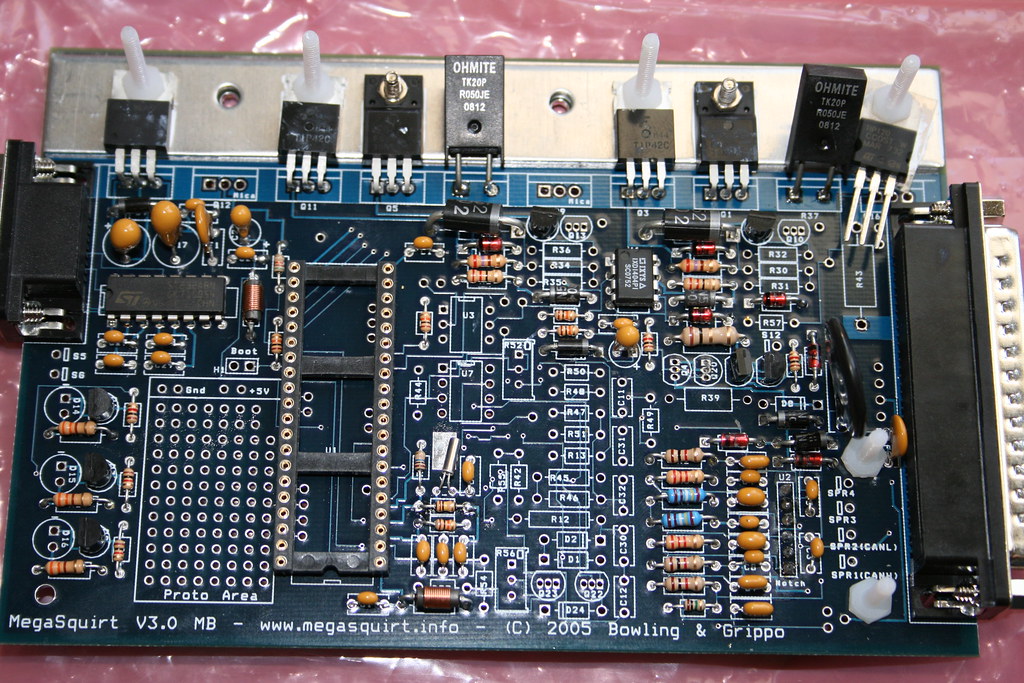
so the build is complete except for a few things which i wasnt sure if i should add or not.

from step 50, d1? d2? i also added r43 afterthe picture was taken because i saw you guys had it on your boards. the led's are still not on ofcourse.. but otherwise i think its done. next i am going to tackle the leads going to q4 for the purple box mod. do they need to be heat shrunk like you guys have? i dont have tools for that.. i do feel more satisfied since the board seems much more complete now.
thanks alot!
Reply
0
0

 07-29-2008, 04:52 PM
#100
The 'protoboard' area is that series of holes off to the bottom left of the picture - this is where you're going to put the op-amp you're going to buy from radioshack, to make two of the circuits I've shown.
While you don't NEED the LED's, I like to have them. I can tell at a glance if the car thinks it's got the fans on, or if the ignition is working.
It looks like it's starting to come together. I'm assuming you skipped all the testing that the megamanual told you to do? You should do that. In order. It's how you keep from frying things. Therefor you'll need to test the power, then the coms, then the chip, and finally all the odds-and-ends inputs and outputs.
Find someone with a jimstim or get one yourself. Had you got on this back when you first started this thread, you'd already have all the testing items you need.
Also, don't forget to check the timing before you go for a drive. I don't want to have to talk you through rebuilding a motor.
Reply
0
0


