Golferlukes megasquirt... take two
 01-20-2011, 06:26 PM
#1
Junior Member
Thread Starter
Join Date: Oct 2009
Location: Springfield, MO
Posts: 492
Total Cats: 3
Some of you might remember I tried to build a ms3 at the end of the summer and never got it running.  Well I got tired of of the frustrastion and decided to go the diypnp route. Since I was chasing my tail on the ms3 project while the group buy was going on I missed it and I'm having to do it all myself. I'm following the DIY autotune write up but I had just a couple of questions.
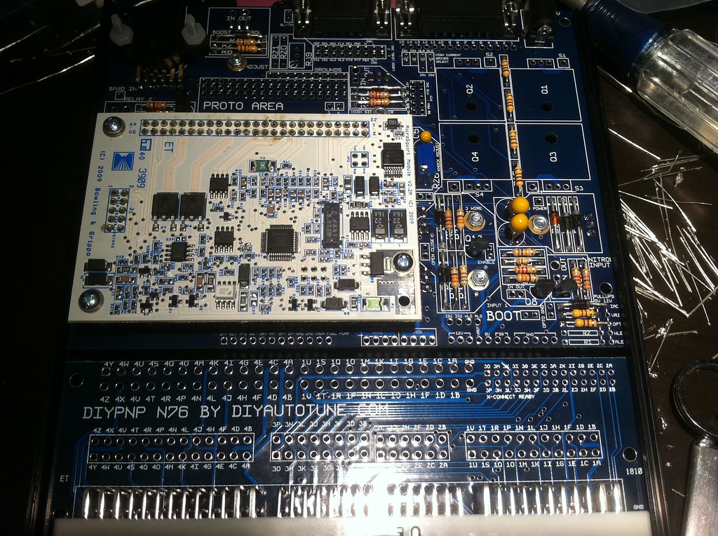
I've just followed the basic "main board assembly" on the diypnp.com site and now that its completed I plan on following the 99-00 specific instructions. Is that the correct path to take? I just installed everything the instructions said to, assuming if I had stuff I don't need (ie boost control) I can just simply not use it. (I've also installed the pullups but thats about it as far as 99 specific stuff goes)
Does it matter what row of holes on the adapter board I solder the jumper wires into? ( question I know)
I have plenty of 12v power cords laying around. Can I use one of them that fits for the diypnp? The power cord I was thinking of using is off my external hard drive and the output is 12v-2A.
Ok last question right now is about the I/O Circuits. In the guide it shows:
Relay 1 _____ Mainboard PA0 ______ ConnectorBoard 1R __ Radiator Fan
Input 1 _____ 1P (remove R14) ____ 1S, 1I _____________ A/C Relay & Fan
On the radiator fan I can't seem to find PA0 lol, were is it?
And for A/C I just remove r14 but then what do I jump 1P to? 1S? 1I? Or am I supposed to make some kind of 2 way split between both 1S and 1I?
EDIT:
Oops, uno mas, do I need to do anything special for knock sensing?
Well I got tired of of the frustrastion and decided to go the diypnp route. Since I was chasing my tail on the ms3 project while the group buy was going on I missed it and I'm having to do it all myself. I'm following the DIY autotune write up but I had just a couple of questions.I've just followed the basic "main board assembly" on the diypnp.com site and now that its completed I plan on following the 99-00 specific instructions. Is that the correct path to take? I just installed everything the instructions said to, assuming if I had stuff I don't need (ie boost control) I can just simply not use it. (I've also installed the pullups but thats about it as far as 99 specific stuff goes)
Does it matter what row of holes on the adapter board I solder the jumper wires into? (
question I know)I have plenty of 12v power cords laying around. Can I use one of them that fits for the diypnp? The power cord I was thinking of using is off my external hard drive and the output is 12v-2A.
Ok last question right now is about the I/O Circuits. In the guide it shows:
Relay 1 _____ Mainboard PA0 ______ ConnectorBoard 1R __ Radiator Fan
Input 1 _____ 1P (remove R14) ____ 1S, 1I _____________ A/C Relay & Fan
On the radiator fan I can't seem to find PA0 lol, were is it?
And for A/C I just remove r14 but then what do I jump 1P to? 1S? 1I? Or am I supposed to make some kind of 2 way split between both 1S and 1I?
EDIT:
Oops, uno mas, do I need to do anything special for knock sensing?
Last edited by Golferluke; 01-20-2011 at 06:42 PM.

Reply
 0
0

0
 01-20-2011, 07:35 PM
#3
Supporting Vendor


iTrader: (33)
Join Date: Jul 2006
Location: atlanta-ish
Posts: 12,659
Total Cats: 134
I've just followed the basic "main board assembly" on the diypnp.com site and now that its completed I plan on following the 99-00 specific instructions. Is that the correct path to take? I just installed everything the instructions said to, assuming if I had stuff I don't need (ie boost control) I can just simply not use it. (I've also installed the pullups but thats about it as far as 99 specific stuff goes)
Does it matter what row of holes on the adapter board I solder the jumper wires into? ( question I know)
question I know)
I have plenty of 12v power cords laying around. Can I use one of them that fits for the diypnp? The power cord I was thinking of using is off my external hard drive and the output is 12v-2A.
Ok last question right now is about the I/O Circuits. In the guide it shows:
Relay 1 _____ Mainboard PA0 ______ ConnectorBoard 1R __ Radiator Fan
Input 1 _____ 1P (remove R14) ____ 1S, 1I _____________ A/C Relay & Fan
On the radiator fan I can't seem to find PA0 lol, were is it?
Relay 1 _____ Mainboard PA0 ______ ConnectorBoard 1R __ Radiator Fan
Input 1 _____ 1P (remove R14) ____ 1S, 1I _____________ A/C Relay & Fan
On the radiator fan I can't seem to find PA0 lol, were is it?
And for A/C I just remove r14 but then what do I jump 1P to? 1S? 1I? Or am I supposed to make some kind of 2 way split between both 1S and 1I?
EDIT:
Oops, uno mas, do I need to do anything special for knock sensing?
Oops, uno mas, do I need to do anything special for knock sensing?
Here's a link to the thread I started when I built mine. I think if you read it, a lot of your questions will be answered:
https://www.miataturbo.net/megasquirt-18/diypnp-99-a-38806/
Reply
0
0
01-20-2011, 07:38 PM
#4
Supporting Vendor
iTrader: (33)
Join Date: Jul 2006
Location: atlanta-ish
Posts: 12,659
Total Cats: 134
Time to get on those jumpers man! I find it easier to remove the microsquirt module when soldering in the jumpers to the mainboard.
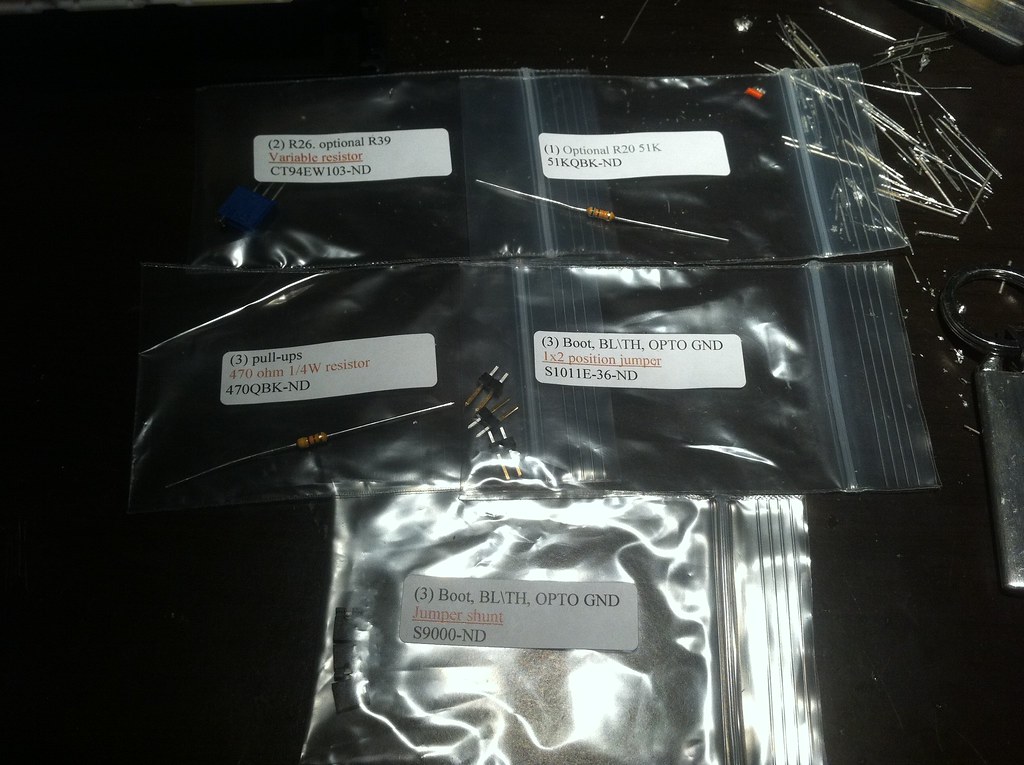
Those are all unneeded parts. With possible exception to the 1x2 postion headers. I would install at least one header at the boot load pins on the board, to make it easier to load firmware. The others are for opto ground (not needed for miata) and blue tooth adapter power at the DB9 (cool feature, but I don't think I've ever seen it used).
Heres what I had left over, I shouldn't need this stuff right?
Reply
0
0
01-20-2011, 09:39 PM
#5
Junior Member
Thread Starter
Join Date: Oct 2009
Location: Springfield, MO
Posts: 492
Total Cats: 3
Great, thank you so much for the help, now that I got food in the belly and a case in the fridge hopefully I'll get this finished up tonight.
If possible I think I'll go with the stock knock sensor unless I really need the other. I'm trying to keep everything stock for now so I can use the stock ecu as well.
I probabbly should have laid out my plans in the first post. My car is completely stock right now besides cops. I have a turbo setup sitting in my closet thats itching to come out but I want to get my engine management handled first. I also have a wideband o2 and gm iat that I will be installing but want to stick to one thing at a time.
So for now I just megasquirt to replace the stock ecu. Then I'll get it working with wideband, then delete the maf, then i should be ready for turbo.
Before I can do any of that though I need to figure out alternator control. As far as I can tell my options are the alt control circuit, external voltage regulator and swapping the alt from an older miata.
I would really like to do the alternator control circuit but theres to many parts that I can't track down without ordering from 10 different places online. My only way to get parts here is radio shack. (Unless somebody has extra and wants to sell me a kit with all the pieces I need )
)
I'm really leaning towards the external voltage regulator though because its alot cheaper than swapping for a miata alt (plus I can't really get one here, I'll have to drive an hour and spend $100) The only problem with that is grounding, I don't have the tools to drill and tap the holes to mount it. Maybe I could zip tie it and then solder the case to the frame lol? Ghetto with a capitol G but anybody see why it wouldnt work? Napa doesn't have that part number any more but i'm pretty sure this is the same.
Oh one more thing, with the 1.5 I don't need ignition drivers right? cause I didn't get any lol
If possible I think I'll go with the stock knock sensor unless I really need the other. I'm trying to keep everything stock for now so I can use the stock ecu as well.
I probabbly should have laid out my plans in the first post. My car is completely stock right now besides cops. I have a turbo setup sitting in my closet thats itching to come out but I want to get my engine management handled first. I also have a wideband o2 and gm iat that I will be installing but want to stick to one thing at a time.
So for now I just megasquirt to replace the stock ecu. Then I'll get it working with wideband, then delete the maf, then i should be ready for turbo.
Before I can do any of that though I need to figure out alternator control. As far as I can tell my options are the alt control circuit, external voltage regulator and swapping the alt from an older miata.
I would really like to do the alternator control circuit but theres to many parts that I can't track down without ordering from 10 different places online. My only way to get parts here is radio shack. (Unless somebody has extra and wants to sell me a kit with all the pieces I need
)I'm really leaning towards the external voltage regulator though because its alot cheaper than swapping for a miata alt (plus I can't really get one here, I'll have to drive an hour and spend $100) The only problem with that is grounding, I don't have the tools to drill and tap the holes to mount it. Maybe I could zip tie it and then solder the case to the frame lol? Ghetto with a capitol G but anybody see why it wouldnt work? Napa doesn't have that part number any more but i'm pretty sure this is the same.
Oh one more thing, with the 1.5 I don't need ignition drivers right? cause I didn't get any lol
Reply
0
0
01-21-2011, 12:07 AM
#6
Senior Member

Join Date: Aug 2010
Location: Maumelle, AR
Posts: 613
Total Cats: 3
You don't need the ignition drivers with your setup (They're built in the toyota coils and thats why the toyota cops are popular) Just to clarify, you aren't planning to drive around on the base maps w/ out a wideband right? I haven't looked, but surely newark or digikey have all the parts for the alternator control circuit, shouldn't be that hard to find, but for $14, I wouldn't be scared of an external regulator either... assuming connectors are easy enough to source. But yeah, you're just not going to solder the case to anything, it wouldn't last very long if you ever got it to stick at all (the frame would definitely suck up almost any amount of heat you throw at it). You shouldn't have to tap anything if you can just find a spot to drill through, and just run a nut and a bolt. I'm probably missing something specifig to these regulators though.
Reply
0
0
01-21-2011, 12:14 AM
#7
Junior Member
Thread Starter
Join Date: Oct 2009
Location: Springfield, MO
Posts: 492
Total Cats: 3
No I don't plan on driving untill I have wbo2 installed and maf deleted. the connector is another $8 at oreilllys. I'm kinda liking the volt reg more and more. Less room for user error :P
PS if I can't get this thing up and running I may have to buy a case and come down to lr to have you help me ha ha.
PS if I can't get this thing up and running I may have to buy a case and come down to lr to have you help me ha ha.
Reply
0
0
01-21-2011, 02:17 AM
#8
Junior Member
Thread Starter
Join Date: Oct 2009
Location: Springfield, MO
Posts: 492
Total Cats: 3
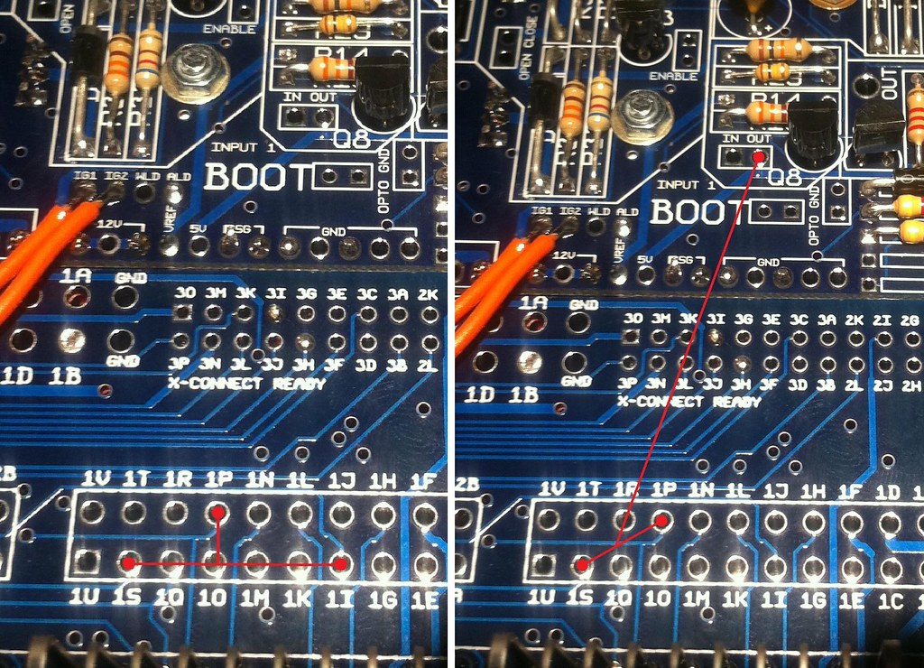
Ok I got all the wiring/jumping done, everything but the ac. But I'm still confused on this. The instructions say 1p to 1s,1i but your saying 1p and 1s and input one's output. I don't know how to explain my question very well so I'll use my amazing ms paint skills.
Left? Right? Neither?
Left? Right? Neither?
Reply
0
0
01-21-2011, 09:46 AM
#9
Senior Member
Join Date: Aug 2010
Location: Maumelle, AR
Posts: 613
Total Cats: 3
No I don't plan on driving untill I have wbo2 installed and maf deleted. the connector is another $8 at oreilllys. I'm kinda liking the volt reg more and more. Less room for user error :P
PS if I can't get this thing up and running I may have to buy a case and come down to lr to have you help me ha ha.
PS if I can't get this thing up and running I may have to buy a case and come down to lr to have you help me ha ha.
 You're on the home stretch though, if you can get it idling, throw the stock ecu back on and I'll be glad to help you tune it.
BTW, you run 1p to the IN port or input 1, neither picture is correct, lol. You're close though, the out pin goes to 1S and 1I. I would wire OUT from input 1 to 1S, then jumper 1l to 1S on the other set of pads so you don't have to run two wires.
Last edited by ianferrell; 01-21-2011 at 10:03 AM.
Reply
0
0
 01-21-2011, 11:28 AM
#11
Junior Member
Thread Starter
Join Date: Oct 2009
Location: Springfield, MO
Posts: 492
Total Cats: 3
Ianferrell I'm free as well, I'll try and get this up and running today. If I do I'll get in touch with you, I'm sure you could use an extra set of hands for the timing belt too.
Reply
0
0
01-21-2011, 02:43 PM
#12
Junior Member
Thread Starter
Join Date: Oct 2009
Location: Springfield, MO
Posts: 492
Total Cats: 3
Ok everything is wired up now and then when I went to load firmware...
**** *****

I can see it fine in device manager, it was originally comm port 5, 3 and 4 are used, I tried using both 1 and 2 but no dice. I'm using firmware 303y, should I be using an older one? the guide says MS2/Extra 3.0.3 || 9-12-09 but I couldn't find one that old.
I'm on vista 32bit, I understand xp would probabbly be easier but theres nothing I can do about that.
**** *****
I can see it fine in device manager, it was originally comm port 5, 3 and 4 are used, I tried using both 1 and 2 but no dice. I'm using firmware 303y, should I be using an older one? the guide says MS2/Extra 3.0.3 || 9-12-09 but I couldn't find one that old.
I'm on vista 32bit, I understand xp would probabbly be easier but theres nothing I can do about that.
Reply
0
0
01-21-2011, 02:57 PM
#13
Senior Member
Join Date: Aug 2010
Location: Maumelle, AR
Posts: 613
Total Cats: 3
Vista should be fine, what usb-> serial adapter are you using? You need to go to device manager and figure out what port its actually on. If you're still having problems I can help you tomorrow, worst case I have an extra usb-> serial that uses the ftdi chipset (which is the best if anyone is looking, screw anything prolific, mixed results out of those at best)
You should just go ahead and load the 3.1 firmware from msextra.com, and then load the diypnp base map on top of that (which is 3.0.3 something) (3.1 firmware http://www.msextra.com/forums/viewto...p?f=91&t=38966 remember to tell it microsquirt module)
edit: Yeah, if you're using the port that device manager says, its almost certainly your usb->serial adapter... Go ahead and get on ebay and search for 'usb serial ftdi' they're more expensive, but who cares because the work, everytime. On second thought I don't really have an 'extra' though I have another cable that might work better, but I might be able to loan you one or at least just get the thing up and running/do some tuning with a ftdi cable.
Reply
0
0
01-21-2011, 03:36 PM
#14
Junior Member
Thread Starter
Join Date: Oct 2009
Location: Springfield, MO
Posts: 492
Total Cats: 3
ok i'll look into 3.1.
Heres the one I'm using.
http://sabrent.com/v2/usb-2-0-to-ser...le-1-ft-cable/
Heres the one I'm using.
http://sabrent.com/v2/usb-2-0-to-ser...le-1-ft-cable/
Reply
0
0
01-21-2011, 03:49 PM
#15
Senior Member
Join Date: Aug 2010
Location: Maumelle, AR
Posts: 613
Total Cats: 3
Yeah. prolific ftl. You can try finding the latest drivers for it, that helps some people. Speaking from experience though, I wouldn't waste much time on it because them er crappy. Get your wideband wired in and MAP hose in there (haven't done one on an NB, its a mild PITA on an NA). What wideband do you have? Really, you could swap over to it, just leave the factory connector disconnected, you'll get a CEL and maybe slightly worse mileage but it'll be fine and we can start tuning sooner. (if its a lc1 or anything with dual outputs you could actually set it to output NB for the factory ECU, and then reprogram it for the DIYPNP... On my car I spliced into the factory O2 wire on the harness side of the ecu connector, so that I don't have a separate connector just for that signal, not a big deal with a DIYPNP, but with a 'boomslang' type setup on a car that will never have the factory ECU again it makes sense.
Reply
0
0
01-21-2011, 03:50 PM
#16
Junior Member
Thread Starter
Join Date: Oct 2009
Location: Springfield, MO
Posts: 492
Total Cats: 3

I was on msextra going through the serial setup instructions to see if i missed something. I used the port checker, well my ms showed up on port two but device manager said port one, well I tried running the .bat on port two while device manager said "com1" and it worked

EDIT: Ya I have a lc1 but no gauge. I'll have to do some reading, I don't really know how to install it.
Last edited by Golferluke; 01-21-2011 at 04:05 PM.
Reply
0
0
01-21-2011, 04:08 PM
#17
Senior Member
Join Date: Aug 2010
Location: Maumelle, AR
Posts: 613
Total Cats: 3
Tunerstudio. Lc1s are easy enough, some ppl bitch but they work. I wish you had an NA as I've figured out the perfect easy way to install them in almost no time Trick is to use the power window connector for the 5a feed and ground lines (they're the big wires) Then run the o2 connector through the body shift boot, and leave the lc1 under the console. To get the best signal, you want to run the other ground line as close to the ecu as you can get (and if you run an analog gauge you'll want to use the same ground point so they'll read the same). On my car I just spliced into the oe harness right in front of the ecu connector, its safe to pulled switch 12v off there too because its only like 100 ma max on that line... you could even run the 'logic' power and ground through the db15 connector in diypnp, but it clearly wouldn't work if you went back to the OE ecu at that point.
Just to clarify, as the LC1 instructions aren't super clear (they say to run the grounds to the same spot)
* LC-1 with 6 stripped ends:
o Red 12V supply -
(this is the line that needs to be good for 5a)
o Blue Heater Ground
(this is just a chasis ground that needs to be good for 5a, can just put a ring terminal on it and stick it on a convenient bolt)
o White System Ground
(small wire, This wire needs to be close to the ECU so there isn't voltage drift)
o Yellow Analog out 1 - gauge, megasquirt, etc.
(both of these outputs are programable, you can set one for NB, or whatever you want)
o Brown Analog out 2 - gauge, megasquirt, etc.
o Black Calibration wire -
(follow instructions)
Trick is to use the power window connector for the 5a feed and ground lines (they're the big wires) Then run the o2 connector through the body shift boot, and leave the lc1 under the console. To get the best signal, you want to run the other ground line as close to the ecu as you can get (and if you run an analog gauge you'll want to use the same ground point so they'll read the same). On my car I just spliced into the oe harness right in front of the ecu connector, its safe to pulled switch 12v off there too because its only like 100 ma max on that line... you could even run the 'logic' power and ground through the db15 connector in diypnp, but it clearly wouldn't work if you went back to the OE ecu at that point.Just to clarify, as the LC1 instructions aren't super clear (they say to run the grounds to the same spot)
* LC-1 with 6 stripped ends:
o Red 12V supply -
(this is the line that needs to be good for 5a)
o Blue Heater Ground
(this is just a chasis ground that needs to be good for 5a, can just put a ring terminal on it and stick it on a convenient bolt)
o White System Ground
(small wire, This wire needs to be close to the ECU so there isn't voltage drift)
o Yellow Analog out 1 - gauge, megasquirt, etc.
(both of these outputs are programable, you can set one for NB, or whatever you want)
o Brown Analog out 2 - gauge, megasquirt, etc.
o Black Calibration wire -
(follow instructions)
Reply
0
0
01-21-2011, 06:15 PM
#18
Junior Member
Thread Starter
Join Date: Oct 2009
Location: Springfield, MO
Posts: 492
Total Cats: 3
First of all, thanks for everyones help so far, I realize I don't know much about this and I appreciate you guys holding my hand through this ha ha. Ok I've been trying to figure out how I'm going to wire up the lc1, I think the plan is just mount the box in the engine bay on the flat area under the brake master cyl. Maybe somebody can chime in with words of wisdom.
12v= I don't know where I'll find one
blue ground= some bolt on the motor
white ground= different bolt on motor (where is the ecu ground?)
yellow signal= Just tap it into existing o2 wire signal wire? Then I won't have to run anything through the firewall.
From what I've been reading the grounds need to be grounded to the same thing, but not on the same bolt correct?
Reply
0
0


