MS DIYPNP v1.5 - EBC & IAT - MAF harness
 04-03-2016, 12:58 PM
#1
Junior Member
Thread Starter

Join Date: Feb 2016
Location: Trondheim, Norway
Posts: 53
Total Cats: 1
Hi, I have two questions.
I have a DIYPNP v1.5 from DIYAutotune.
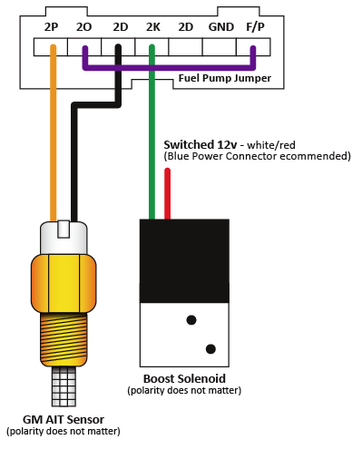
1. I soldered the jumpers for the IAT as per instructions to 4P, and under the hood, also per instructions, connected the IAT to the MAF harness to socket 1 and 6. Everything is working, and the car has been running great for a long time, and still is, with the wiring like this.
But when I look at the wiring diagram it appears that the socket 6 is going to ECU pin 4O. I have not jumped anything to 4O, why am I still reading the correct air temp?

2. I have installed and wired an EBC solenoid from DIYautotune. PA0 to 4K via boost circuit. I havent mounted my turbo yet. Is it a way from i.e Tunerstudio or other to verify my wiring is sound and the solenoid is operational?
Thanks
I have a DIYPNP v1.5 from DIYAutotune.
1. I soldered the jumpers for the IAT as per instructions to 4P, and under the hood, also per instructions, connected the IAT to the MAF harness to socket 1 and 6. Everything is working, and the car has been running great for a long time, and still is, with the wiring like this.
But when I look at the wiring diagram it appears that the socket 6 is going to ECU pin 4O. I have not jumped anything to 4O, why am I still reading the correct air temp?
2. I have installed and wired an EBC solenoid from DIYautotune. PA0 to 4K via boost circuit. I havent mounted my turbo yet. Is it a way from i.e Tunerstudio or other to verify my wiring is sound and the solenoid is operational?
Thanks

Reply
 0
0

0


 04-03-2016, 02:52 PM
#3
Junior Member
Thread Starter
Join Date: Feb 2016
Location: Trondheim, Norway
Posts: 53
Total Cats: 1
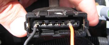
I'm trying but the only way I can get the picture of the pins in the connector to hook up with 4P if I number the sockets backwards alphabetical
G pin#1 goes to 4P
B pin#6 goes to Ground
But I highly doubt this is the correct way of reading the diagram.
G pin#1 goes to 4P
B pin#6 goes to Ground
But I highly doubt this is the correct way of reading the diagram.
Reply
0
0