Worlds ugliest MS3Pro Module install
 03-13-2016, 09:30 AM
#1
Senior Member
Thread Starter

Join Date: Apr 2011
Location: Hollywood, FL
Posts: 807
Total Cats: 163
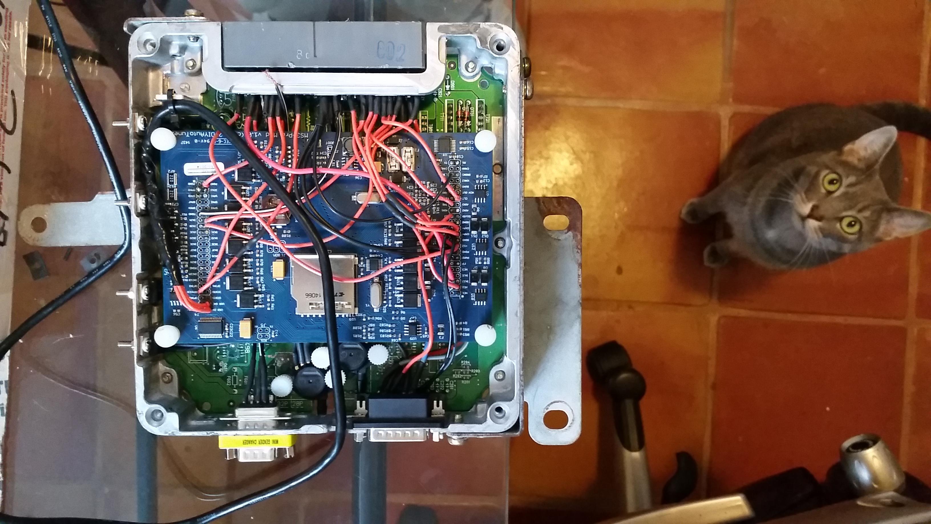
So finally after 2+ years of purchasing this thing and various delays caused by life I finally have the car running with a MS3! It's a pro module stuffed in the factory ecu housing. Instead of pressing the easy button and just getting one of Frank's adapter boards I went this route as I have some modifications to the wiring harness that would not allow me to use his boards directly. I could have bought the weather sealed MS3Pro but then I would have to make a harness anyhow with a DIYBOB plus its an extra $300 or so. I decided to be cheap.
A little history on how I got to the current configuration:
Since I have a DIYPNP running the car I wanted to mimic the mods done to that to be able to quickly swap between ecu's had there been a problem. Not that the ecu's are problematic, just that my soldering skills and understanding of electronics are sub-par so I wanted to go back to a known quantity in case things started acting up.
The car is a 95.5 with a VVT swap. I run SCCA autox and when I swapped in the VVT engine I didn't see in the rules where it said you could modify the harness by cutting and splicing and I didn't want to add a bunch of wires for the cam/crank sensors. What I did was use the closest sensor connectors for 12v, ground, and signal wires to get back to the ecu. This meant the MAF signal is my crank sensor, the cas is my cam signal, and vvt actuator is through the purge solenoid. Later on when I added COP I used BIP373's inside the DIYPNP. This caused lots of noise issues (thanks to this board for pointing this out) as I was sharing the ecu's ground. So I backfed ground through the original coil signal wires from the back of the head. Noise issue solved. And of course now I have the DB15 of the DIYPNP being used for spark and the wbo2 input. So an adapter board not specifically made for these mods would have been an issue.
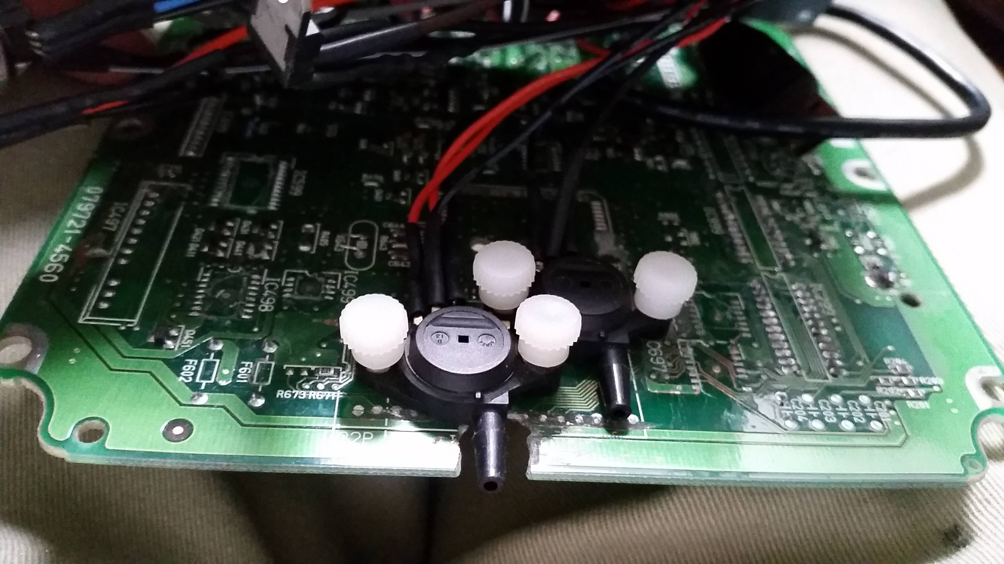
On to getting the factory housing to accept the pro module. It was a matter of finding a place to heat sink the BIP373's, removing as much components off the factory board as possible so I could uss it as a base for attaching the module and the map and baro sensors. Making holes to the case for the DB15 and DB9, map sensor hose, and USB cable. And of course cutting all the connections from the header to the plug so I could solder my jumpers to the ecu.
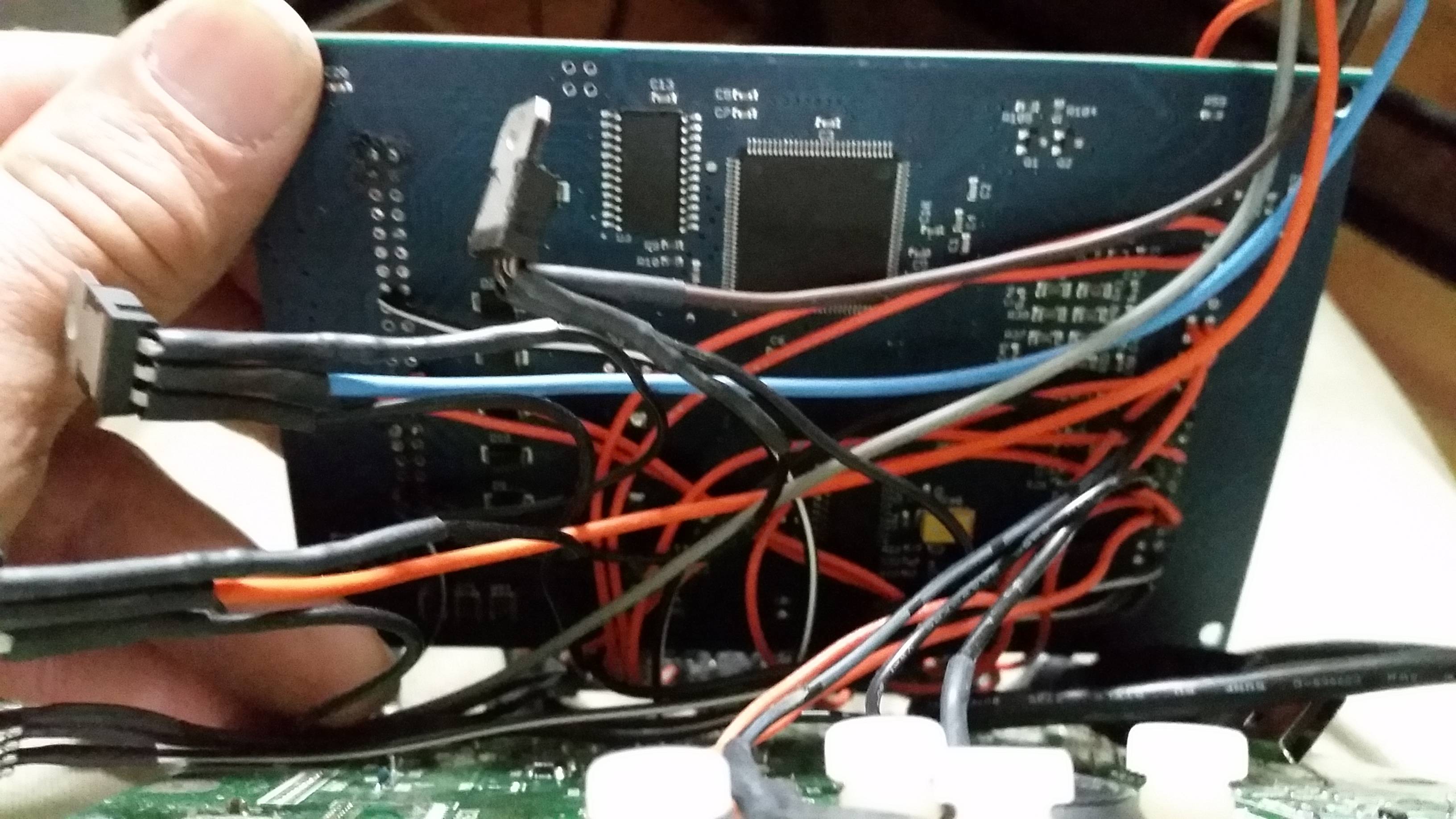
I kinda messed up by not adding headers to the ecu and just soldering the jumpers straight to the board. It made it much more difficult for my 43yo eyes and awful soldering skills. But at the same time it allowed to put jumpers that went to the top row of the ecu connector on top and the bottom ones below. Had I located the module further back on the housing this may ot have been an issue but I wanted the extra space at the back for the DB connector installation.
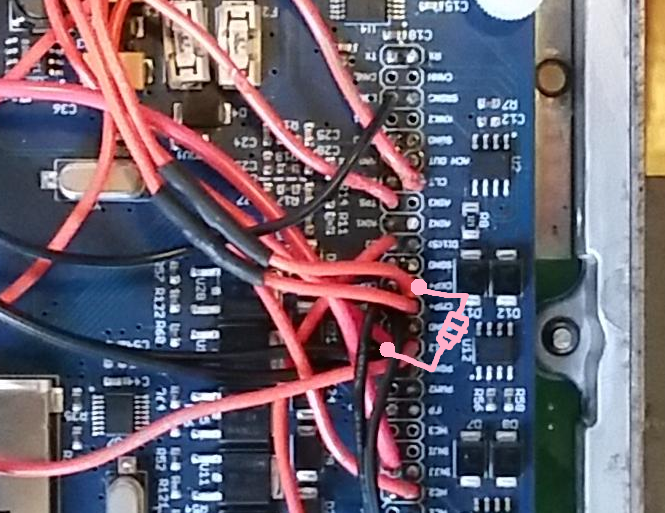
Once I got everything sorted out is was on to the car to see if all this work worked! Of course it didn't. After a whole day trying different settings, getting the injector and ignition outputs and fuel pump working but car not running, going back to the DIYPNP and having the car not start either, figuring out it was a dirty/faulty ground issue not letting it sync, I finally read the instructions. I had to put a 1K resistor on the signal wires to 12v from the crank/cam sensor in order for thing to sync. Once I did that, all was good. Except now the DIPNP doesn't sync! Oh well, I'll be selling that I guess.
So I loaded all the pertinent tune parameters from my old ecu and the car ran great. Now I have to set-up the vvt to work again. Plus I am also adding flex fuel. That will be in the coming weeks. I also have to get a working idle control valve as when I went to ITB's a year ago I haven't had working idle control.
Lastly I have to make a comparator circuit for the AC control as now I don't have AC! Matt from DIYAuto gave me the bad news that the miata has some funky AC request signal that has variable voltage or something. Anyhow, anyone have any experience with this? Maybe the Brain knows? Obviously the DIYPNP has some circuit built into it that can handle the signal as it worked with that ecu.
Anyhow, a couple of pics:
A little history on how I got to the current configuration:
Since I have a DIYPNP running the car I wanted to mimic the mods done to that to be able to quickly swap between ecu's had there been a problem. Not that the ecu's are problematic, just that my soldering skills and understanding of electronics are sub-par so I wanted to go back to a known quantity in case things started acting up.
The car is a 95.5 with a VVT swap. I run SCCA autox and when I swapped in the VVT engine I didn't see in the rules where it said you could modify the harness by cutting and splicing and I didn't want to add a bunch of wires for the cam/crank sensors. What I did was use the closest sensor connectors for 12v, ground, and signal wires to get back to the ecu. This meant the MAF signal is my crank sensor, the cas is my cam signal, and vvt actuator is through the purge solenoid. Later on when I added COP I used BIP373's inside the DIYPNP. This caused lots of noise issues (thanks to this board for pointing this out) as I was sharing the ecu's ground. So I backfed ground through the original coil signal wires from the back of the head. Noise issue solved. And of course now I have the DB15 of the DIYPNP being used for spark and the wbo2 input. So an adapter board not specifically made for these mods would have been an issue.
On to getting the factory housing to accept the pro module. It was a matter of finding a place to heat sink the BIP373's, removing as much components off the factory board as possible so I could uss it as a base for attaching the module and the map and baro sensors. Making holes to the case for the DB15 and DB9, map sensor hose, and USB cable. And of course cutting all the connections from the header to the plug so I could solder my jumpers to the ecu.
I kinda messed up by not adding headers to the ecu and just soldering the jumpers straight to the board. It made it much more difficult for my 43yo eyes and awful soldering skills. But at the same time it allowed to put jumpers that went to the top row of the ecu connector on top and the bottom ones below. Had I located the module further back on the housing this may ot have been an issue but I wanted the extra space at the back for the DB connector installation.
Once I got everything sorted out is was on to the car to see if all this work worked! Of course it didn't. After a whole day trying different settings, getting the injector and ignition outputs and fuel pump working but car not running, going back to the DIYPNP and having the car not start either, figuring out it was a dirty/faulty ground issue not letting it sync, I finally read the instructions. I had to put a 1K resistor on the signal wires to 12v from the crank/cam sensor in order for thing to sync. Once I did that, all was good. Except now the DIPNP doesn't sync! Oh well, I'll be selling that I guess.
So I loaded all the pertinent tune parameters from my old ecu and the car ran great. Now I have to set-up the vvt to work again. Plus I am also adding flex fuel. That will be in the coming weeks. I also have to get a working idle control valve as when I went to ITB's a year ago I haven't had working idle control.
Lastly I have to make a comparator circuit for the AC control as now I don't have AC! Matt from DIYAuto gave me the bad news that the miata has some funky AC request signal that has variable voltage or something. Anyhow, anyone have any experience with this? Maybe the Brain knows? Obviously the DIYPNP has some circuit built into it that can handle the signal as it worked with that ecu.
Anyhow, a couple of pics:

Reply
 0
0

0
03-13-2016, 12:19 PM
#5
Senior Member
Thread Starter
Join Date: Apr 2011
Location: Hollywood, FL
Posts: 807
Total Cats: 163
Haha! I will, just not right now!
Honestly I could have re-wired the car and then I could have used Franks board which would have made it look 1,000 times better. But I hate working on the car with electronics and would rather do soldering in my house. Plus I actually like the look of how I have it wired up.
I also could have not soldered in the pins from the connector to the adapter board and have a jumper from the module straight to the pin. It would have been an abortion of Franks board but it would have made 90% of the work easy.
Like I said, I did it this way hoping I could swap between ecu's in case of whatever. No longer the case so in the future if I really get sick of looking at this thing the way it is I will contact Frank and hope he has some boards left.
Now, have any of you gents something to share on the AC not working with this ecu? Have any of you had issues with this? How have you resolved it?
I saw that Brain did a DIYBOB harness for a MS3 Pro module and it appeared to be Miata specific. Did that car have AC? Did it work or did you do some stuff in the proto area?
Reply
0
0
03-14-2016, 07:26 AM
#6
Boost Czar


iTrader: (62)
Join Date: May 2005
Location: Chantilly, VA
Posts: 79,490
Total Cats: 4,079
There's nothing special about a/c, it's an input and an output: Put the a/c switch on a digital switched in, then the relay output on a spare injector driver or PWM out.
frank's board would have been easier than what you ended up doing. yours is just such a mess. it doesnt matter what it looks like, it's just the ease and function. if yours works, then more power to you -- doesnt matter if it's an utter mess in there :P
frank's board would have been easier than what you ended up doing. yours is just such a mess. it doesnt matter what it looks like, it's just the ease and function. if yours works, then more power to you -- doesnt matter if it's an utter mess in there :P
Reply
0
0
03-14-2016, 09:23 PM
#7
Senior Member
Thread Starter
Join Date: Apr 2011
Location: Hollywood, FL
Posts: 807
Total Cats: 163
I will keep trying different digital inputs. I tried DI4 which is supposed to be digital switched 12v but that does nothing. The folks at DIYAutotune said they run a comparator circuit on the MSPNP Pro and I would likely have to do the same. Some digging around on the web found that the Input 1 & 2 circuits on the DIYPNP are exactly this and obviously the AC worked with the DIYPNP.
But yes I know it looks atrocious and it made assembling it much more difficult. To understand my decision you also need to understand the circumstances. Having said that, Frank's board isn't always going to be available so some other enclosure type like a DIYPNP enclosure with the connector and adapter board and some kinda bread board holding the module with headers would work nicely. Or at least look better. But when all else fails, at least what I did works.
And yes it works just fine and I am happy after 2 1/2 years to finally have the thing running the car. I now have a CEL, speedo input to the ecu, real time clock, hopefully real AC control, soon FLEX fuel, and native VVT control with the ITB fuel load as opposed to the VVTuner which can only see map (unless you rigged it to the TPS). Plus all the other incrementally better things about the MS3 over MS2, and even more so, MS3 Pro over MS3.
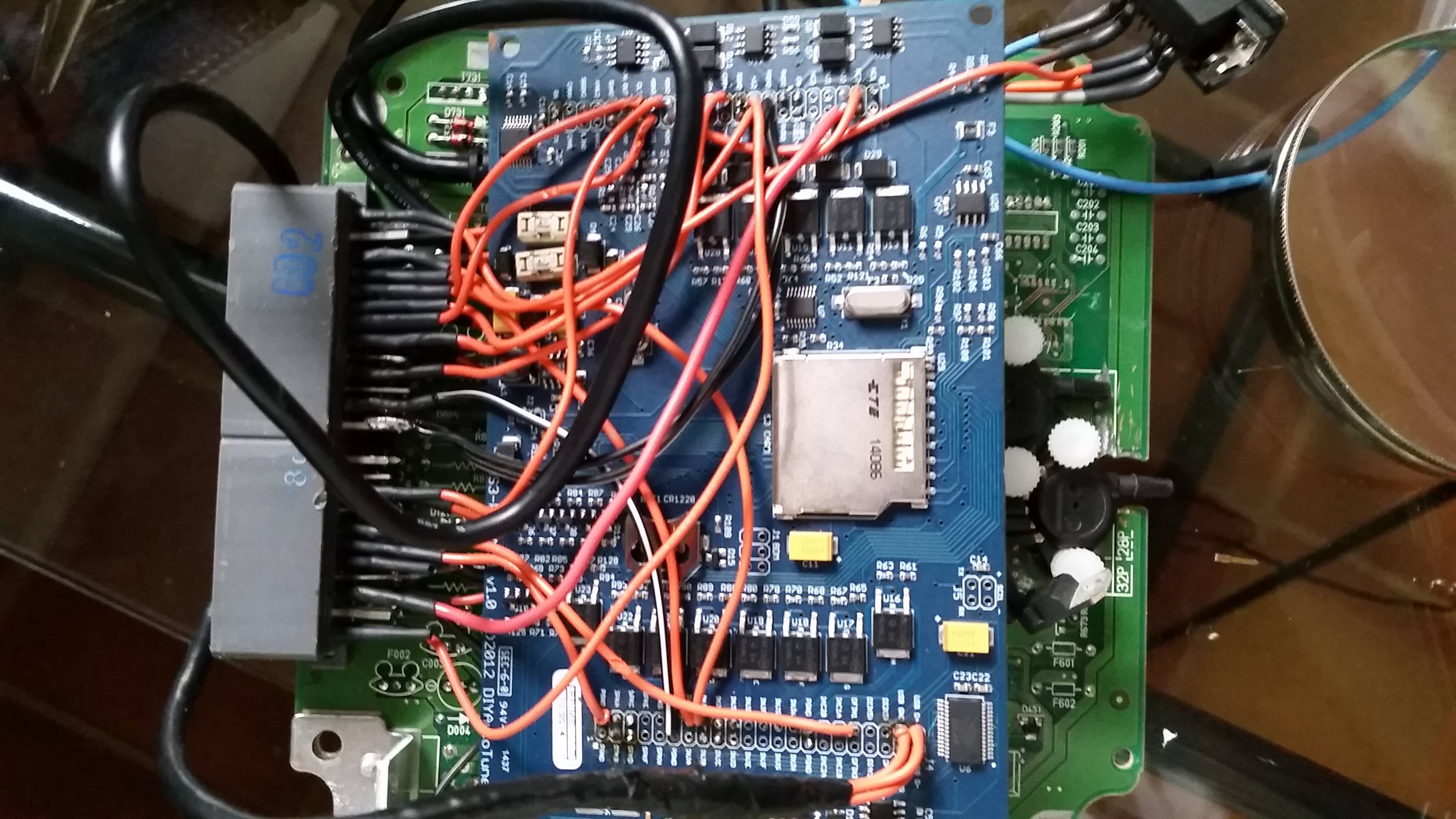
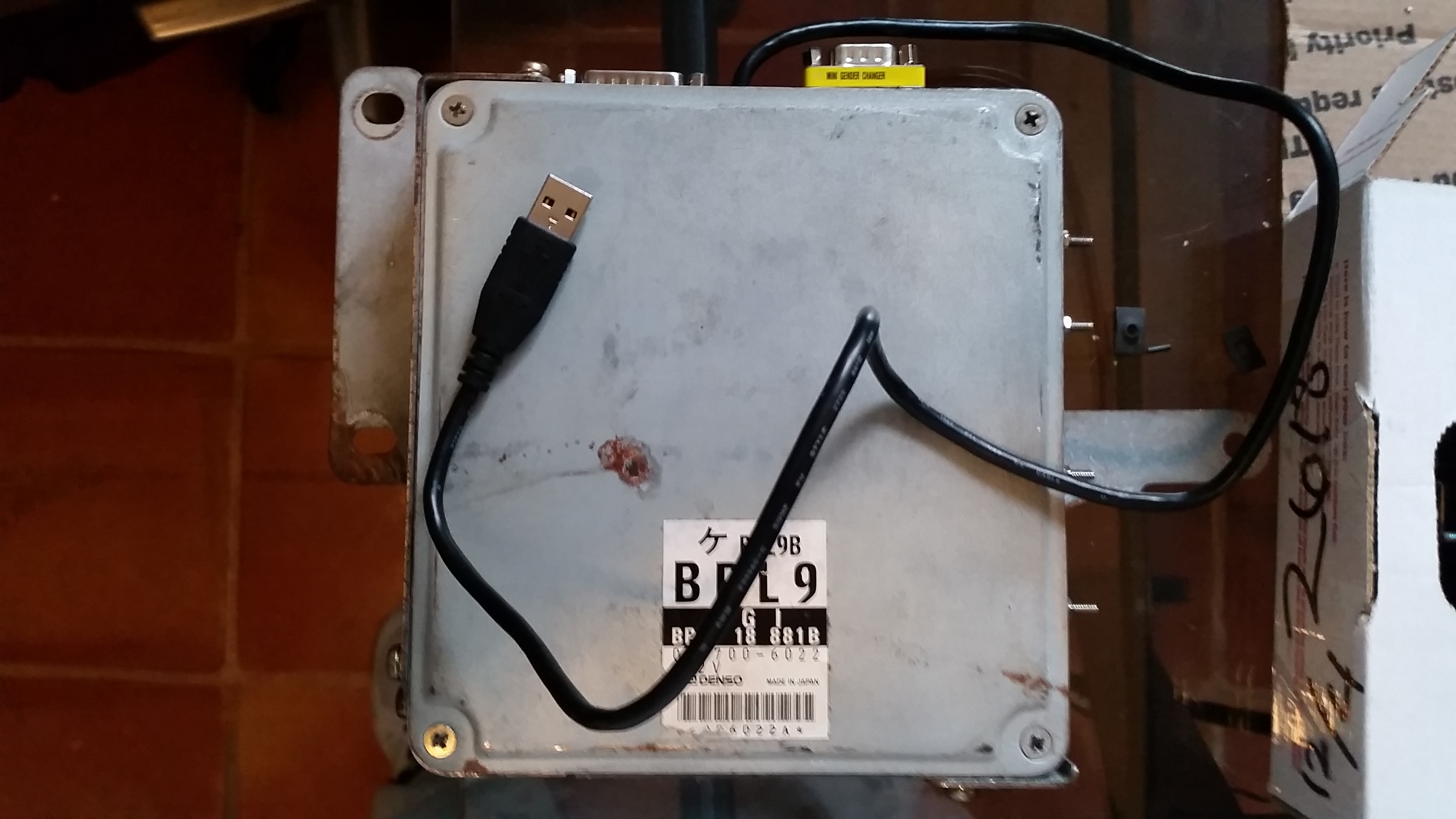
But since you liked my work so much, here are some pics of the finished product. You can see my helper in one of them.
But yes I know it looks atrocious and it made assembling it much more difficult. To understand my decision you also need to understand the circumstances. Having said that, Frank's board isn't always going to be available so some other enclosure type like a DIYPNP enclosure with the connector and adapter board and some kinda bread board holding the module with headers would work nicely. Or at least look better. But when all else fails, at least what I did works.
And yes it works just fine and I am happy after 2 1/2 years to finally have the thing running the car. I now have a CEL, speedo input to the ecu, real time clock, hopefully real AC control, soon FLEX fuel, and native VVT control with the ITB fuel load as opposed to the VVTuner which can only see map (unless you rigged it to the TPS). Plus all the other incrementally better things about the MS3 over MS2, and even more so, MS3 Pro over MS3.
But since you liked my work so much, here are some pics of the finished product. You can see my helper in one of them.
Reply
0
0
03-15-2016, 08:12 AM
#8
Boost Czar
iTrader: (62)
Join Date: May 2005
Location: Chantilly, VA
Posts: 79,490
Total Cats: 4,079
you just need a spare input and spare output. You CANT use a 12v input for a switched ground (that input is pretty much useless) -- try again.
there's nothing special about it whatsoever.
the a/c switch goes to ground, when the MS sees the ground it does whatever your parameters demand in the idle-up menu, and then it activates the a/c relay through the output you put it on.
I usually use DI 1-2-3 for VSS, a/c switch, and the clutch switch. (at least on MS3x)
You should be able to use Digital Freq. in instead. You should at least put VSS on the dig. freq. in if youre using that on a DI, and put the a/c switch there.
pretty certain all 6 of those inputs (DI and DF) work interchangeability.
Last edited by Braineack; 03-15-2016 at 08:27 AM.
Reply
0
0
03-20-2016, 11:10 AM
#9
Senior Member
Thread Starter
Join Date: Apr 2011
Location: Hollywood, FL
Posts: 807
Total Cats: 163
Well it seems the Brain>DIYAutotune support at least on the matter of the AC input. It worked as you mentioned with the input on DFI3.
I have DFI1 for VSS. And DI1 for FLEX as there is no other supported input for FLEX.
Question for any of you: Did you all have to put a resistor from signal to 12V on the cam and crank in order for it to sync? I had to do it to mine. I have a 1k resistor in there.
The car had been running great until I got the AC going and now i'm having intermittent sync losses. I wonder if my placement of the resistor under the hood in the sensor harness is not playing well with the additional heat produced by running the AC? Maybe I should try a higher watt resistor or lower resistance?
Reply
0
0
03-20-2016, 12:01 PM
#10
Boost Czar
iTrader: (62)
Join Date: May 2005
Location: Chantilly, VA
Posts: 79,490
Total Cats: 4,079
I use a 1K to 5v. 12v might cause the issue youre seeing.
I would be putting it in the ecu case.
but you could do a composite log and see which sensor youre dropping.
I would be putting it in the ecu case.
but you could do a composite log and see which sensor youre dropping.
Reply
0
0
03-20-2016, 12:07 PM
#11
Senior Member
Thread Starter
Join Date: Apr 2011
Location: Hollywood, FL
Posts: 807
Total Cats: 163
Composite log shows the crank sensor dropping. The resistor for that is in a rather high heat area just above the radiator in front of the engine. Will try moving them inside the case. More ugly work for me.
Reply
0
0

 04-07-2016, 12:35 PM
#16
Junior Member

Join Date: Dec 2008
Location: Ft. Lauderdale, FL
Posts: 315
Total Cats: 9
Hector, will you be at the ER event this weekend? I would like to take a look at your adaptor board... lol.
I might try to do something similar (minus hacking up the stock ECU board) but using the harness plug.
Frank, I sent you an email via your website inquiring about your board on Monday and I got no response yet. Do you still have them available for '99+ cars? I would to ask you some questions about it as my install would not be a standard install. I am in the planning stages of swapping a VVT motor into a '99 and I think it is going to be way easier to use the existing cam sensor wires for the VVT solenoid and the existing VICS wires for the VVT cam sensor. Wondering if your board would be able to handle that kind of change.
Reply
0
0
04-07-2016, 01:16 PM
#17
Senior Member

Join Date: Nov 2007
Location: Belgium
Posts: 999
Total Cats: 73
Sorry 'bout that, I thought I had replied. Unfortunately I don't have 99+ boards at the moment. There was very little interest (2 persons I believe) and I need to sell 5 of them to not loose money on this. I have the design ready though, so if there's more interest, I might just make a batch.
Reply
0
0
04-07-2016, 02:40 PM
#18
Junior Member
Join Date: Dec 2008
Location: Ft. Lauderdale, FL
Posts: 315
Total Cats: 9
Sorry 'bout that, I thought I had replied. Unfortunately I don't have 99+ boards at the moment. There was very little interest (2 persons I believe) and I need to sell 5 of them to not loose money on this. I have the design ready though, so if there's more interest, I might just make a batch.
Reply
0
0
04-07-2016, 07:49 PM
#19
Senior Member
Thread Starter
Join Date: Apr 2011
Location: Hollywood, FL
Posts: 807
Total Cats: 163
DJ, I'll be at BB&T Sunday. I'll let you have the honor of taking out the passenger seat to get to the ecu.
Frank thanks so much for making these boards. I hope to be a candidate for one someday.
Oh and I finally got working idle control with the ITB's. IAC valve from the 01 VVT TB works perfect with some PEX fittings and JB Weld! No more having to cut AC compressor off as I push in the clutch.
And Brain I moved the resistors inside the ecu and to 5v. So far no loss of sync in my short drives.
Reply
0
0

Thread
Thread Starter
Forum
Replies
Last Post
Ruined_miata
General Miata Chat
6
03-13-2016 09:33 AM
Ruined_miata
General Miata Chat
3
03-12-2016 07:05 PM


