MS1 3.57 upgrade to MS2 - questions/help
 10-08-2008, 02:30 AM
#1
Elite Member
Thread Starter

Join Date: Mar 2006
Location: Schwarzenberg, Germany
Posts: 1,553
Total Cats: 101
I hope Brain doesn't mind, that I take this out of my original build thread, because it seems to get lost there.
Hi guys,
as I don't seem to have success with my MS1 attempt - I choose to go on and go the way it should be working - standalone MS2
I ordered the following at DIYautotune:
>> [SM-WireBund] $12,00
>> [MS2-DB] CPU - MegaSquirt-II Daughterboard $90,00
>> [mk-RelayCtrl] - PCBv3 and v2.2 -- Relay Control 'ModKit' (VTEC, TVIS,
>> Fans] $5,00
>> [mk-PWMIAC] - PCBv3 -- PWM IAC Valve Control (TIP120) 'Mod-Kit' $7,00
So I did some research on what I need to mod at the board - I would be really thankful if someone could confirm and/or correct or add to it.
Thanks!
MS1 (3.57) to MS2
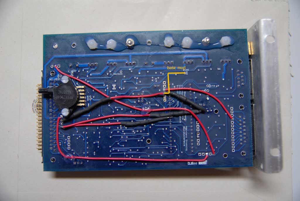
The basic changes should be:
Remove the old chip - bring 12V to JS9 from S12C
picture:

The mods to the board described in post 1 of this thread have to be changed:
1. MOD_13571... Modifications for Miata / DSM ignition
In this picture from the MS2 manual it says R1 has to be removed - correct?

How about the input mods - I am going to use Abe's circuit so what would have to be removed from the board?
2. MOD_1357-... Add boost control mod-kit to V3.57 board
The boost output comes out at JS2 - I think that can stay unchanged.
3.MOD_1357-... Launch control input mod on pin 29
Launch control input comes in at JS11 - I also think that can stay unchanged. (Correct?)
4. MOD_1357-... Add jumper for KnockSenseMS to
Megasquirt-I V3.57 Run a jumper from
JS10 to DB15 pin 3.[/INDENT]
Knock input is at JS10 which at the MS2 is dedicated to the 2nd trigger input. So I have to move this to JS4 or JS5. See this pin usage chart - pin usage
Thats all for the mods that are already done to the board:
New mods for the standalone situation should be:
Idle valve control:
V3.57 PCB, this is a little tricky so care must be taken. Fit the TIP122 and solder a wire to the base of it and to the right side of R19, next to U8. Then connect the Collector to SPR1 (you can use any of the db15 pads if you wish) and the emittor of the TIP122 connect to a GND pad on the V3.57 pcb. This will give you the FIdle valve output on pin 3 of the db37 connector (or what ever connector the pad you used is connected to), do not use the standard FIdle output connector on pin 30 of the db37. The TIP122 can be mounted on the case or in place of R37 on the heatsink if R37 is linked out, remember it MUST be insulated!
A IN4001 will need to be fitted across the Idle valve, to do this install it externally (on the wiring to the valve is fine) by connecting the banded side of the diode to the 12V supply on the valve and the non-banded side to the FIdle output wire (depends on which SPR connector you used internally)

Could I wire the IN4001 also inside the MS case? I don't see, why this has to be made outside...
One more thing - at the DIYautotune website it says about the Idle mod kit:
This kit will work with both the V2.2 and V3.0 PCBs. (Not needed on PCB 3.57 SMT ECUs)
Why is that?
Fan mod
I have no idea...
--------------------
This should be all of the mods to the board - of course I would have to do the NB alternator mod.
I got no VICS (1,6) and no A/C - so no need to worry about that.
That is what I know as of today - any input is appreciated.
Thanks
Sven
Hi guys,
as I don't seem to have success with my MS1 attempt - I choose to go on and go the way it should be working - standalone MS2
I ordered the following at DIYautotune:
>> [SM-WireBund] $12,00
>> [MS2-DB] CPU - MegaSquirt-II Daughterboard $90,00
>> [mk-RelayCtrl] - PCBv3 and v2.2 -- Relay Control 'ModKit' (VTEC, TVIS,
>> Fans] $5,00
>> [mk-PWMIAC] - PCBv3 -- PWM IAC Valve Control (TIP120) 'Mod-Kit' $7,00
So I did some research on what I need to mod at the board - I would be really thankful if someone could confirm and/or correct or add to it.
Thanks!
MS1 (3.57) to MS2
The basic changes should be:
Remove the old chip - bring 12V to JS9 from S12C
picture:
The mods to the board described in post 1 of this thread have to be changed:
1. MOD_13571... Modifications for Miata / DSM ignition
input and output on a V3.57 board. The
CKP signal comes in on pin 24 and the
CMP signal comes in on pin 25. Spark
output A comes out on pin 36, and spark
output B comes out on pin 31.
The spark output mods should be unchanged.CKP signal comes in on pin 24 and the
CMP signal comes in on pin 25. Spark
output A comes out on pin 36, and spark
output B comes out on pin 31.
In this picture from the MS2 manual it says R1 has to be removed - correct?
How about the input mods - I am going to use Abe's circuit so what would have to be removed from the board?
2. MOD_1357-... Add boost control mod-kit to V3.57 board
and bring output out on pin 27 on the
DB37.
EDIT: I had a mistake here - boost output comes out at JS2 (not JS0 as originally written)of courseDB37.
The boost output comes out at JS2 - I think that can stay unchanged.
3.MOD_1357-... Launch control input mod on pin 29
Launch control input comes in at JS11 - I also think that can stay unchanged. (Correct?)
4. MOD_1357-... Add jumper for KnockSenseMS to
Megasquirt-I V3.57 Run a jumper from
JS10 to DB15 pin 3.[/INDENT]
Knock input is at JS10 which at the MS2 is dedicated to the 2nd trigger input. So I have to move this to JS4 or JS5. See this pin usage chart - pin usage
Thats all for the mods that are already done to the board:
New mods for the standalone situation should be:
Idle valve control:
V3.57 PCB, this is a little tricky so care must be taken. Fit the TIP122 and solder a wire to the base of it and to the right side of R19, next to U8. Then connect the Collector to SPR1 (you can use any of the db15 pads if you wish) and the emittor of the TIP122 connect to a GND pad on the V3.57 pcb. This will give you the FIdle valve output on pin 3 of the db37 connector (or what ever connector the pad you used is connected to), do not use the standard FIdle output connector on pin 30 of the db37. The TIP122 can be mounted on the case or in place of R37 on the heatsink if R37 is linked out, remember it MUST be insulated!
A IN4001 will need to be fitted across the Idle valve, to do this install it externally (on the wiring to the valve is fine) by connecting the banded side of the diode to the 12V supply on the valve and the non-banded side to the FIdle output wire (depends on which SPR connector you used internally)
Could I wire the IN4001 also inside the MS case? I don't see, why this has to be made outside...
One more thing - at the DIYautotune website it says about the Idle mod kit:
This kit will work with both the V2.2 and V3.0 PCBs. (Not needed on PCB 3.57 SMT ECUs)
Why is that?
Fan mod
I have no idea...
--------------------
This should be all of the mods to the board - of course I would have to do the NB alternator mod.
I got no VICS (1,6) and no A/C - so no need to worry about that.
That is what I know as of today - any input is appreciated.
Thanks
Sven
Last edited by Zaphod; 10-14-2008 at 02:37 AM.

Reply
 0
0

0
10-08-2008, 09:46 AM
#2
Supporting Vendor

Join Date: Sep 2006
Posts: 2,332
Total Cats: 67
How about the input mods - I am going to use Abe's circuit so what would have to be removed from the board?]
2. MOD_1357-... Add boost control mod-kit to V3.57 board
and bring output out on pin 27 on the
DB37.
The boost output comes out at JS0 - I think that can stay unchanged.
DB37.
3.MOD_1357-... Launch control input mod on pin 29
Launch control input comes in at JS11 - I also think that can stay unchanged. (Correct?)
4. MOD_1357-... Add jumper for KnockSenseMS to
Megasquirt-I V3.57 Run a jumper from
JS10 to DB15 pin 3.[/INDENT]
Knock input is at JS10 which at the MS2 is dedicated to the 2nd trigger input. So I have to move this to JS4 or JS5. See this pin usage chart - pin usage
Megasquirt-I V3.57 Run a jumper from
JS10 to DB15 pin 3.[/INDENT]
Knock input is at JS10 which at the MS2 is dedicated to the 2nd trigger input. So I have to move this to JS4 or JS5. See this pin usage chart - pin usage
Idle valve control:
V3.57 PCB, this is a little tricky so care must be taken. Fit the TIP122 and solder a wire to the base of it and to the right side of R19, next to U8. Then connect the Collector to SPR1 (you can use any of the db15 pads if you wish) and the emittor of the TIP122 connect to a GND pad on the V3.57 pcb. This will give you the FIdle valve output on pin 3 of the db37 connector (or what ever connector the pad you used is connected to), do not use the standard FIdle output connector on pin 30 of the db37. The TIP122 can be mounted on the case or in place of R37 on the heatsink if R37 is linked out, remember it MUST be insulated!
A IN4001 will need to be fitted across the Idle valve, to do this install it externally (on the wiring to the valve is fine) by connecting the banded side of the diode to the 12V supply on the valve and the non-banded side to the FIdle output wire (depends on which SPR connector you used internally)
Could I wire the IN4001 also inside the MS case? I don't see, why this has to be made outside...
Reply
0
0
10-08-2008, 10:46 AM
#4
Elite Member
Thread Starter
Join Date: Mar 2006
Location: Schwarzenberg, Germany
Posts: 1,553
Total Cats: 101
Hi Matt, (and the others)
I have just seen at my board, that the launch controll input comes in at JS9 at my board - which will in the future provide 12V to teh MS2 board.
Where would you move the launch input to usually?
JS4 or JS5 maybe?
Greets
I have just seen at my board, that the launch controll input comes in at JS9 at my board - which will in the future provide 12V to teh MS2 board.
Where would you move the launch input to usually?
JS4 or JS5 maybe?
Greets
Reply
0
0
10-08-2008, 01:01 PM
#5
Boost Pope


iTrader: (8)
Join Date: Sep 2005
Location: Chicago. (The less-murder part.)
Posts: 33,026
Total Cats: 6,592
Zaphod, sorry for coming into this a bit late.
This site: http://www.msextra.com/ms2extra/ will give you all the information you need to know. In particular, there is a section on converting to the MS2, and then the one below that (MS2-Extra Hardware Manual) will give you every pin and pad designation you need to know.
Launch control, on the MS2, can be done on JS4, JS5, JS7, JS10, or JS11.
reference: http://www.msextra.com/ms2extra/MS2-...are.htm#launch
Reply
0
0
10-08-2008, 02:59 PM
#6
Elite Member
Thread Starter
Join Date: Mar 2006
Location: Schwarzenberg, Germany
Posts: 1,553
Total Cats: 101
Hi Joe,
I know and read the MS2 site. I thought someone would share some usual ways to do things.
And for some things I need some - easier understandable - knowledge, because I am sometimes a bit unsure how to do things right, because of the very specific technical language...
I am happy about every comment.
Thanks
Greets
Reply
0
0
10-08-2008, 03:50 PM
#7
Boost Pope
iTrader: (8)
Join Date: Sep 2005
Location: Chicago. (The less-murder part.)
Posts: 33,026
Total Cats: 6,592
I understand. Just pointing out that there is no single standard for a lot of these features (such as launch control.) You can use any of the ports I listed that are available.
Reply
0
0
10-09-2008, 06:35 AM
#9
Elite Member
Thread Starter
Join Date: Mar 2006
Location: Schwarzenberg, Germany
Posts: 1,553
Total Cats: 101
I did some homework.
As I think, that the informations I collected maybe interesting for at least some people, I will try to write them down.
(This is for the upgrade of a MS1 3.57 board to MS2 for a 99 Miata)
1. basic mod
Pull a jumper wire between S12c (12V) and JS9
As you can see, some wires have to be removed to achieve this, but as it really is "the basic mod" I changed the order a little bit there.
2. CMP mod/ CKP mod
Completly remove the old CMP/CKP mod (which was done for 90-97 CAS)
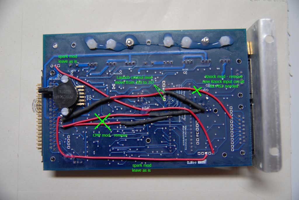
(CKP mod is at the other side - I think it's just the R57 which you have to remove at a modded 3.57 board)
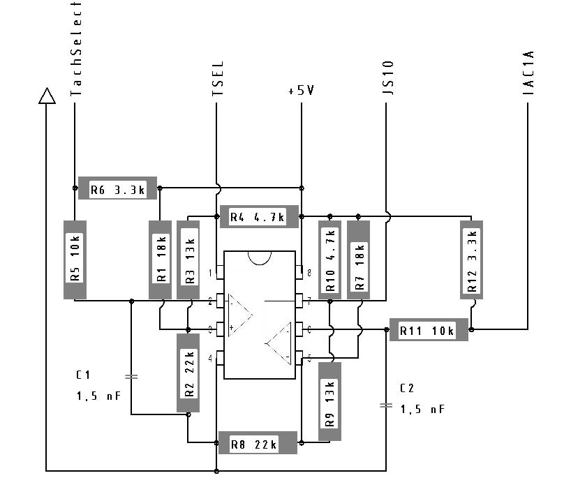
Now add Abe's circuit to the CMP / CKP input as shown in the circuit .

On a 3.57 board there are some different terms/descriptions for the inputs/outputs printed on the board.
CKP:
comes in at DB37 pin 24
Tach select(3.0) is JP1 pin2(3.57) ---> Abe's circuit --> Tsel(3.0) is J1 pins 2-4-6(3.57)
CMP:
comes in at DB37 pin 25
IAC1A(3.0 = 3.57) (not SPR1 as shown in the pic) ---> Abe's circuit --> JS10(3.57)
3. spark mod
stays unchanged - (see pic above)
4. launch mod
move from JS 9 (which is 12 V to MS2 daugtherboard in the future to JS7. (or other pin according to http://www.msextra.com/ms2extra/MS2-...htm#ms2options)
5. Knock control mod
The knock control mod (wire between DB15 pad 15 and JS10) has to be removed to my understanding and replaced by the following mod.

As the 3.57 board has no proto area - I will try to build a little proto board inside the MS housing for Abe's circuit and the knock mods - as well as for the upcomming standalone mods.
End of part 1
-------------------------
If someone has seen mistakes or has suggestions, feel free to reply.
As I think, that the informations I collected maybe interesting for at least some people, I will try to write them down.
(This is for the upgrade of a MS1 3.57 board to MS2 for a 99 Miata)
1. basic mod
Pull a jumper wire between S12c (12V) and JS9
As you can see, some wires have to be removed to achieve this, but as it really is "the basic mod" I changed the order a little bit there.
2. CMP mod/ CKP mod
Completly remove the old CMP/CKP mod (which was done for 90-97 CAS)
(CKP mod is at the other side - I think it's just the R57 which you have to remove at a modded 3.57 board)
Now add Abe's circuit to the CMP / CKP input as shown in the circuit .
On a 3.57 board there are some different terms/descriptions for the inputs/outputs printed on the board.
CKP:
comes in at DB37 pin 24
Tach select(3.0) is JP1 pin2(3.57) ---> Abe's circuit --> Tsel(3.0) is J1 pins 2-4-6(3.57)
CMP:
comes in at DB37 pin 25
IAC1A(3.0 = 3.57) (not SPR1 as shown in the pic) ---> Abe's circuit --> JS10(3.57)
3. spark mod
stays unchanged - (see pic above)
4. launch mod
move from JS 9 (which is 12 V to MS2 daugtherboard in the future to JS7. (or other pin according to http://www.msextra.com/ms2extra/MS2-...htm#ms2options)
5. Knock control mod
The knock control mod (wire between DB15 pad 15 and JS10) has to be removed to my understanding and replaced by the following mod.
As the 3.57 board has no proto area - I will try to build a little proto board inside the MS housing for Abe's circuit and the knock mods - as well as for the upcomming standalone mods.
End of part 1
-------------------------
If someone has seen mistakes or has suggestions, feel free to reply.
Reply
0
0
10-09-2008, 08:22 AM
#10
Supporting Vendor
Join Date: Sep 2006
Posts: 2,332
Total Cats: 67
I did some homework.
As I think, that the informations I collected maybe interesting for at least some people, I will try to write them down.
(This is for the upgrade of a MS1 3.57 board to MS2 for a 99 Miata)
1. basic mod
Pull a jumper wire between S12c (12V) and JS9
As you can see, some wires have to be removed to achieve this, but as it really is "the basic mod" I changed the order a little bit there.
2. CMP mod/ CKP mod
Completly remove the old CMP/CKP mod (which was done for 90-97 CAS)
(CKP mod is at the other side - I think it's just the R57 which you have to remove at a modded 3.57 board)
Completly remove the old CMP/CKP mod (which was done for 90-97 CAS)
(CKP mod is at the other side - I think it's just the R57 which you have to remove at a modded 3.57 board)
Reply
0
0
10-10-2008, 05:13 AM
#13
Elite Member
Thread Starter
Join Date: Mar 2006
Location: Schwarzenberg, Germany
Posts: 1,553
Total Cats: 101
Hi,
I got all the parts in for Abe's circuit and made myself a layout, how I will try to solder all that components onto a grid-board.
Could the experts have a look, if I got everything correct, (I am a engineer, but not an electronics engineer...)
Original pic of the circuit:
My layout:
Thanks
Sven
I got all the parts in for Abe's circuit and made myself a layout, how I will try to solder all that components onto a grid-board.
Could the experts have a look, if I got everything correct, (I am a engineer, but not an electronics engineer...)
Original pic of the circuit:
My layout:
Thanks
Sven
Reply
0
0
10-13-2008, 11:50 AM
#14
Elite Member
Thread Starter
Join Date: Mar 2006
Location: Schwarzenberg, Germany
Posts: 1,553
Total Cats: 101
More news,
I built the circuit (pics to follow)
and
I got the MS2 daughterboard today. (Only 1 week from ordering to delivery here in Germany - quite a good time)
Installed the circuit this afternoon and after some problems with getting the MS2 firmware installed I get good readings with the Jimstim. Rpm, pulsewidth, wbo2, inj & ign led's are flashing...., temp readings work.
I have to redo my boomslang for a first try to start, over the winter I will go the standalone route - only 3 weeks left this season (car is only running from April to October)
Should I have a look how much off the timing is with the fuel pump relay pulled first?
Greets
Reply
0
0
10-13-2008, 12:15 PM
#15
Boost Pope
iTrader: (8)
Join Date: Sep 2005
Location: Chicago. (The less-murder part.)
Posts: 33,026
Total Cats: 6,592
Instead, disconnect X14, which (on the US spec cars, anyway) is an 8 position connector which houses the fuel injector control leads.

Reply
0
0
10-14-2008, 03:09 AM
#17
Elite Member
Thread Starter
Join Date: Mar 2006
Location: Schwarzenberg, Germany
Posts: 1,553
Total Cats: 101
I did edit post 1 a little bit - I had a mistake with tha boost output - boost output comes out at JS2 (MS1) and stays also unchanged for MS2.
It's AAAAAlive!
Update - 10/14/2008 - 5.18 pm
first some pics of my "Abe circuit"
front:
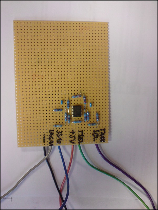
back:
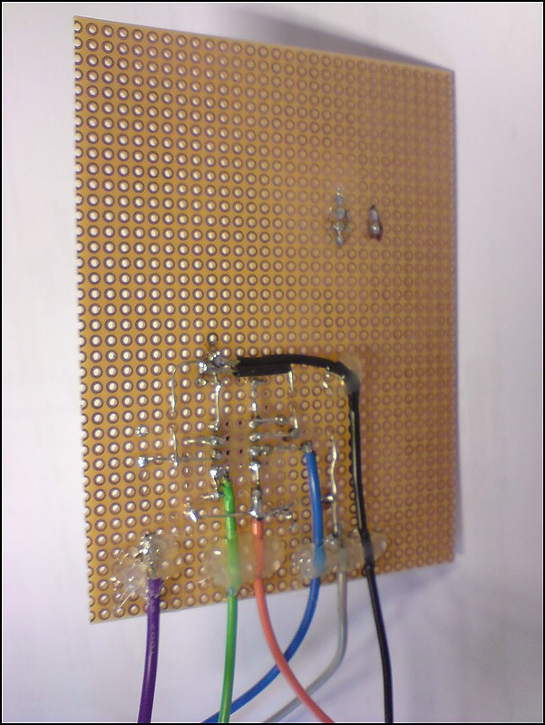
The circuit is made after the drawing above - a little place consuming but quite neat.
Then I drilled some holes into the board and used some plastic push-in threads and some computer screws to hot-glue the circuit into the lid of the MS-case (so I am able to unscrew the board and add the fan mod and other mods)
parts
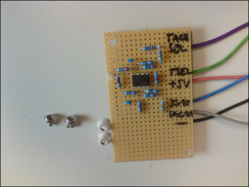
from the back
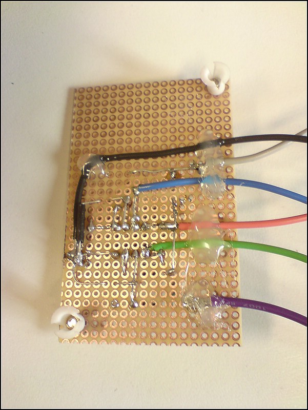
detail of the "plastic push in threads"

Installed inside the lid:
Got a MSQ from Abe for the MS2 which I changed for the needs of my car - turn key - run!
It is running fuel and spark now as parallel install at the moment.
Hope I can take a little tour tomorrow and see if I get it dialed in a bit...
Greets (the happy) German MS 99 1.6
Sven
It's AAAAAlive!
Update - 10/14/2008 - 5.18 pm
first some pics of my "Abe circuit"
front:
back:
The circuit is made after the drawing above - a little place consuming but quite neat.
Then I drilled some holes into the board and used some plastic push-in threads and some computer screws to hot-glue the circuit into the lid of the MS-case (so I am able to unscrew the board and add the fan mod and other mods)
parts
from the back
detail of the "plastic push in threads"
Installed inside the lid:
Got a MSQ from Abe for the MS2 which I changed for the needs of my car - turn key - run!
It is running fuel and spark now as parallel install at the moment.
Hope I can take a little tour tomorrow and see if I get it dialed in a bit...
Greets (the happy) German MS 99 1.6
Sven
Last edited by Zaphod; 10-14-2008 at 11:34 AM.
Reply
0
0
10-15-2008, 12:06 PM
#18
Elite Member
Thread Starter
Join Date: Mar 2006
Location: Schwarzenberg, Germany
Posts: 1,553
Total Cats: 101
Just a quick update - did the first couple of miles (kilometers of course) today - car runs fine, VE tables need to get a little dialed in, other than that - car runs fine.
Greets
Sven
Greets
Sven
Reply
0
0
10-16-2008, 04:14 PM
#20
Elite Member
Thread Starter
Join Date: Mar 2006
Location: Schwarzenberg, Germany
Posts: 1,553
Total Cats: 101
Thanks Joe, I got a lot of help from a lot of guys here - that helped a lot not to loose the energy with this project.
I did the MS (DB37) side of the standalone harness today. I am not entirely sure about the factory immobilizer though, which is standard over here. I suppose I have to take it out and and jumper two of the wires going in and out of the unit. (I'll post a pic out of the wiring diagramm tomorrow)
Greets
Reply
0
0


