MS3 crank position sensor wiring
 04-29-2013, 09:53 AM
#1
Senior Member
Thread Starter
iTrader: (1)

Join Date: Jan 2013
Location: Jacksonville FL
Posts: 648
Total Cats: 216
I'm wiring up the CPS on my MS3'd 99 using a DIYBOB to interface to the OEM under hood wiring-
Should I run the Shielded Twisted Pair wire on the MS3 harness all the way out to the CPS, or is it OK to just run it to the BOB and use the OEM harness from there?
Thanks-
Should I run the Shielded Twisted Pair wire on the MS3 harness all the way out to the CPS, or is it OK to just run it to the BOB and use the OEM harness from there?
Thanks-

Reply
 0
0

0
04-29-2013, 10:41 AM
#3
Senior Member
Thread Starter
iTrader: (1)
Join Date: Jan 2013
Location: Jacksonville FL
Posts: 648
Total Cats: 216
I was born in 1963 to a middle class family in a small town in suburban NJ. Even as a young child I showed an unusual interest in modifying cars, buying several plastic model kits at a time, dumping the contents onto my desk and mixing and matching their parts to build them the way I wanted them. At 13 I sold a Kawasaki KM100 dirt bike my parents bought me to finance the purchase of my first real car, a 1971 Javelin, which I spent the next three years rebuilding. Since then I've owned hundreds of different vehicles.
;^)
If you mean "backstory on this specific project", I'm swapping an 04 MSM drivetrain into my neat-o but underpowered '99 Miata, largely motivated by a track-day ****-talking session in which I boasted that I didn't need my Lotus Elise to put the smack-down on a buddy's new and very fast but poorly driven M3, stating that I could lap his *** in my Miata. I believe I invoked the term "girl car" several times in baiting him into a small wager, but carefully avoided mentioning that I was considering turbocharging the car to accomplish this feat. The 99's motor had a lot of hard miles and was getting tired, and the trans had started getting "gronchy" on up shifts, so I found a low-ish mile drivetrain from a wrecked Mazdaspeed, with the six speed and sourced a 3.90 LSD from an 05 car. I bought a built-up MS3X from DIY AutoTune along with their 12' harnesses and a DIYBOB.
As you all know based on my stupid Noob questions, I'm slogging my way through wiring the MS3, and am at the CPS circuit now. DIY AutoTune went to the trouble of putting a spiffy shielded twisted pair wire to carry the CPS signal, which I'm guessing was to prevent electrical noise from getting to that signal, but the OEM harness went to no such lengths, making me wonder if the DIY Harness (being generic) did so for cars which had a different type of CPS (hall vs VR) than the Miata has.
Hence, my original question; given that the clever little engineers didn't bother with a Shielded twisted pair for the CPS, do I need to, or can I just terminate that STP wire in the DIYBOB like the rest of my MS wiring? Or, is there something specific about the MS3 that requires the STP wire to run all the way out to the stock CPS?
Reply
0
0
04-29-2013, 10:49 AM
#4
Boost Czar


iTrader: (62)
Join Date: May 2005
Location: Chantilly, VA
Posts: 79,490
Total Cats: 4,079
tl;dr: are you replacing the engine harness or something?
But I think the answer you need is: just use two spare unused normal wires for the CMP/CKP wires in your diybob harness.
But I think the answer you need is: just use two spare unused normal wires for the CMP/CKP wires in your diybob harness.
Reply
0
0
04-29-2013, 11:03 AM
#5
Senior Member
Thread Starter
iTrader: (1)
Join Date: Jan 2013
Location: Jacksonville FL
Posts: 648
Total Cats: 216
No, I've left the engine harness in place, only modifying it where the sensor connectors were different, and to connect the MSM coils. Otherwise it's an OEM '99 engine harness plugged into the DIYBOB under the dash where the original ECU was. (I've mounted the MS3X in the old passenger airbag space, so I can just pop off the old airbag cover to access it for tuning. The MS3X harness just runs from the MS to the drivers footwell where the DIYBOB is located.)
Thanks for the answer; I'm trying to keep it all looking as neat as possible, and terminating that STP in the BOB will save me the trouble of running it through the firewall.
Thanks for the answer; I'm trying to keep it all looking as neat as possible, and terminating that STP in the BOB will save me the trouble of running it through the firewall.
Reply
0
0
05-07-2013, 09:44 AM
#7
Senior Member
Thread Starter
iTrader: (1)
Join Date: Jan 2013
Location: Jacksonville FL
Posts: 648
Total Cats: 216
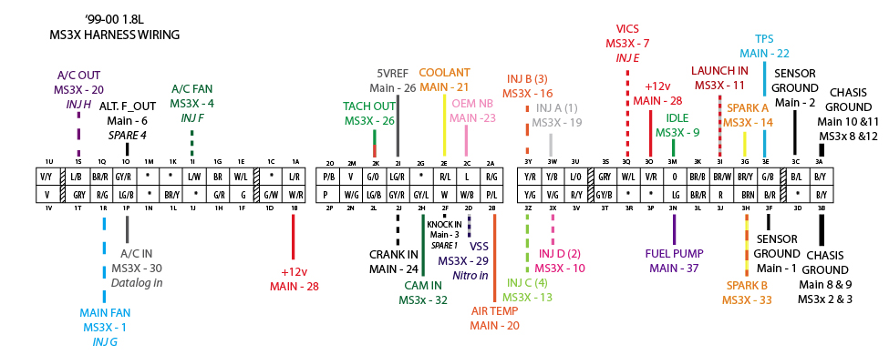
Ok, I'm down to wiring the CPS into the MS3 and just want to make sure I'm doing this correctly-
Looking at the diagrams, it looks like I only have to connect MS24 to the Grey/Red wire that terminated in the original ECU's pin 2J. The White/Red continues to get it's switched 12v from the main relay, and the Black/Blue continues to go to ground.
MS1, the ground wire twisted into the Shielded Twisted Pair then just runs to the same ground as all the rest of my grounds.
Am I right?
Last edited by Pinky; 05-07-2013 at 09:48 AM. Reason: Clarity
Reply
0
0
05-07-2013, 11:00 AM
#9
Senior Member
Thread Starter
iTrader: (1)
Join Date: Jan 2013
Location: Jacksonville FL
Posts: 648
Total Cats: 216
Got it- that's what I said above, MS24 to 2J. Coolness. And the MS1 ground wire in that twisted pair to my One Huge Ground, or can I just clip it off since all grounds are connected in the MS3?
Reply
0
0
05-07-2013, 11:04 AM
#10
Boost Czar
iTrader: (62)
Join Date: May 2005
Location: Chantilly, VA
Posts: 79,490
Total Cats: 4,079
I don't understand what you are saying.
For grounds connect
MS-1 to 3C
MS-2 to 3F
MS-8 & MS-9 to 3A
MS3X-2 & MS3X-3 to 3B
If you're going to run your own grounds, then run MS3X-2,3,8,12,17 and MS-8,9,10,11,12,13 all through individual 18awg wires to one spot on the engine block.
Keep 3C and 3F to MS-1 and MS-2.
For grounds connect
MS-1 to 3C
MS-2 to 3F
MS-8 & MS-9 to 3A
MS3X-2 & MS3X-3 to 3B
If you're going to run your own grounds, then run MS3X-2,3,8,12,17 and MS-8,9,10,11,12,13 all through individual 18awg wires to one spot on the engine block.
Keep 3C and 3F to MS-1 and MS-2.
Reply
0
0
05-07-2013, 12:12 PM
#11
Senior Member
Thread Starter
iTrader: (1)
Join Date: Jan 2013
Location: Jacksonville FL
Posts: 648
Total Cats: 216
Awesome- thank you so much, the grounds had me sort of confused; the MS docs seemed to say that the grounds were all connected inside the MS box, so I was having a hard time understanding why they provided a bazillion ground wires in the harness. I'll do it the way you've said.
I really appreciate all your help.
I really appreciate all your help.
Reply
0
0
05-07-2013, 12:40 PM
#13
Senior Member
Thread Starter
iTrader: (1)
Join Date: Jan 2013
Location: Jacksonville FL
Posts: 648
Total Cats: 216
Ok, now I'm thoroughly confused. The wiring diagram that DIY AutoTune provided with their harness is different than the non-DIY AutoTune diagram I've found online. I've wired everything so far using their diagram, and have connected their MS7 Sensor Ground to 3F already. but haven't connected any other grounds to anything.
I'm attaching both diagrams- does DIY wire their units differently or something??
I'm attaching both diagrams- does DIY wire their units differently or something??
Reply
0
0
05-07-2013, 12:44 PM
#15
Boost Czar
iTrader: (62)
Join Date: May 2005
Location: Chantilly, VA
Posts: 79,490
Total Cats: 4,079
are you directly referencing grounds?
pins 1, 2, 7, 8, 9, 10, 11, 12, 13, 14, 15, 16, 17, 18, 19 all connect at the MS so in all honesty it doesnt really matter, but it's important that you dont try to ground your MS to sensor grounds, with are 3C and 3F, where the cam sensors, tps, clt, ait, etc all ground through and back to the ECU.
why dont you use the digrams I have made?
Reply
0
0
05-07-2013, 12:50 PM
#16
Senior Member
Thread Starter
iTrader: (1)
Join Date: Jan 2013
Location: Jacksonville FL
Posts: 648
Total Cats: 216
are you directly referencing grounds?
pins 1, 2, 7, 8, 9, 10, 11, 12, 13, 14, 15, 16, 17, 18, 19 all connect at the MS so in all honesty it doesnt really matter, but it's important that you dont try to ground your MS to sensor grounds, with are 3C and 3F, where the cam sensors, tps, clt, ait, etc all ground through and back to the ECU.
why dont you use the digrams I have made?
pins 1, 2, 7, 8, 9, 10, 11, 12, 13, 14, 15, 16, 17, 18, 19 all connect at the MS so in all honesty it doesnt really matter, but it's important that you dont try to ground your MS to sensor grounds, with are 3C and 3F, where the cam sensors, tps, clt, ait, etc all ground through and back to the ECU.
why dont you use the digrams I have made?
Reply
0
0
05-07-2013, 12:55 PM
#17
Boost Czar
iTrader: (62)
Join Date: May 2005
Location: Chantilly, VA
Posts: 79,490
Total Cats: 4,079
why are you working from scratch when there are writeups and documents that tell you exactly what to do?
example:

http://westfieldmx5.devocht.com/?s=99-05
example:
http://westfieldmx5.devocht.com/?s=99-05
Reply
0
0
05-07-2013, 01:31 PM
#18
Senior Member
Thread Starter
iTrader: (1)
Join Date: Jan 2013
Location: Jacksonville FL
Posts: 648
Total Cats: 216
why are you working from scratch when there are writeups and documents that tell you exactly what to do?
example:
99-05 | Zoekresultaten | Frank's Westfield MX5 Zoekresultaten 99-05 | & Megasquirt site
example:
99-05 | Zoekresultaten | Frank's Westfield MX5 Zoekresultaten 99-05 | & Megasquirt site
Ugh. That's the first time I've ever seen those.. I've just been trying to figure this thing out without coming off like I want to be spoon-fed.
Thanks for sharing those diagrams; I'm going to go back through my connections and make any changes necessary.
Reply
0
0
08-25-2013, 07:45 PM
#19
Newb

Join Date: Jan 2010
Posts: 3
Total Cats: 0
why are you working from scratch when there are writeups and documents that tell you exactly what to do?
example:
99-05 | Zoekresultaten | Frank's Westfield MX5 Zoekresultaten 99-05 |
example:
99-05 | Zoekresultaten | Frank's Westfield MX5 Zoekresultaten 99-05 |
This is being done so that I can add both a wideband O2 sensor and control the VVT on the 2001 engine that is currently being driven by the stock 99 ECU. I really got excited when you said ,"why are you working from scratch when there are writeups and documents that tell you exactly what to do?" since that was exactly what I seemed to be doing.
I'm just having a hard time finding them.
Thanks In Advance for any pointers you can send me.
Steve
Reply
0
0


