How To: MS-1/MSPNP EBC
 01-09-2012, 07:33 PM
#1
Elite Member
Thread Starter
iTrader: (4)

Join Date: Mar 2008
Location: Granbury, TX
Posts: 6,301
Total Cats: 696
This thread is a combination of the pertinent information from the following two threads:
https://www.miataturbo.net/megasquirt-18/ms1-mspnp-closed-loop-ebc-works-well-my-car-details-60323/
https://www.miataturbo.net/megasquirt-18/how-ms-1-mspnp-closed-loop-ebc-62706/
It is condensed here to present a how-to on setting up EBC with the MS-1 or MSPNP. Three posts follow containing discussion on:
1. Wastegate Control
2. Open Loop EBC
3. Closed Loop EBC
YMMV!

Reply
 2
2

2
01-09-2012, 07:36 PM
#2
Elite Member
Thread Starter
iTrader: (4)
Join Date: Mar 2008
Location: Granbury, TX
Posts: 6,301
Total Cats: 696
EBC should be approached in building block style, with the first step being to ensure that the basic wastegate functionality is working. This is what my basic Greddy wastegate control looks like on a 3rd gear pull:
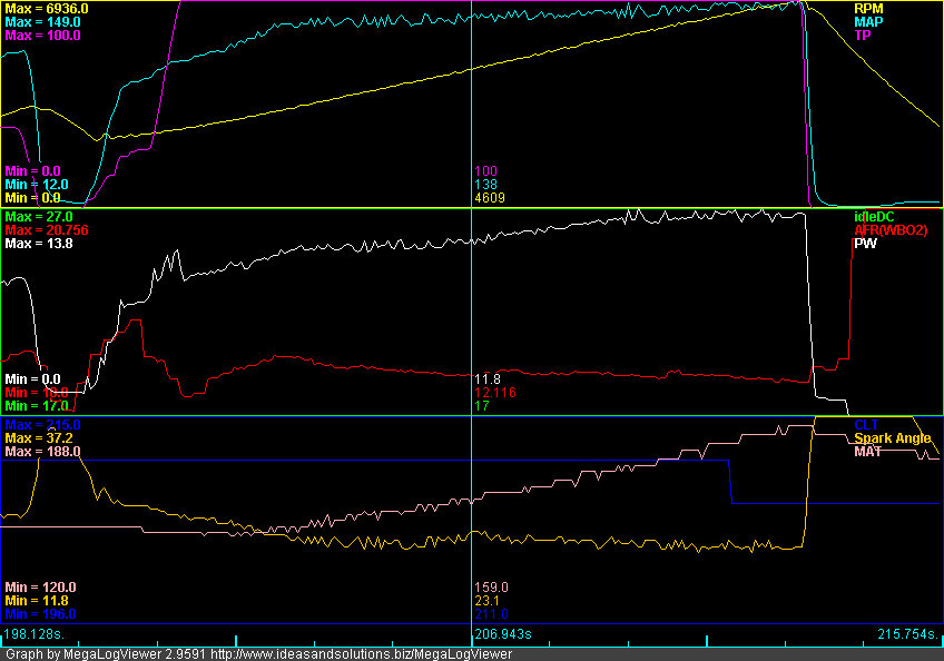
Overall, the control isn't bad. The wastegate kicks in at around 3300RPM and 5.2psi of boost. From 3300RPM to 6900RPM, there is a gradual 2.5psi of boost creep. Two things contribute to boost creep on my car:
1. I don't run an intercooler, therefore there is no pressure loss as the intake flow increases with RPM.
2. I run a performance cat and a 2.5" exhaust which gives less back pressure than stock. I use the stock Greddy downpipe with some porting.
This tends to skew more of the exhaust flow through the turbine instead of the wastegate as flow increases.
Before delving into any form of EBC, you need to ensure that your wastegate basically works so that your boost control has a chance of controlling things. Also, your target boost needs to be higher than the maximum boost generated by the wastegate. The curve here is easily controllable and my boost target of 10psi is comfortably above 7.7psi. So, on to the next step.
Reply
2
2
01-09-2012, 07:39 PM
#3
Elite Member
Thread Starter
iTrader: (4)
Join Date: Mar 2008
Location: Granbury, TX
Posts: 6,301
Total Cats: 696
The next step is Open Loop EBC. Follow the directions in the MSPNP manual for this. Basically, you:
1. Setup the valve parameters;
2. Disable closed loop control; and
3. Tune valve duty cycle targets.
For valve parameters, I bought the DIY EBC valve and just used the defaults. Didn't mess with it. Seems to work.
There are a couple of ways to disable the closed loop control. The MSPNP manual recommends setting all cells of your "Boost kPa Target" table to 70kPa and the "Closed Loop kPa Limit" to 20kPa. Thus, so long as your MAP is at 90kPa or above (as it will be in boost), you will be beyond the "Closed Loop kPa Limits" and operating on the open loop duty cycles.
The other way to disable closed loop control is simply to set 0 as the "Closed Loop kPa Limit." Due to the normal noise on the MAP signal, this condition will never be true except for rare, momentary transitions.
Tuning the valve duty cycles is straightforward. What I did was log a series of third gear pulls with my entire duty cycle table set to a contant value. I would do the third gear pull until I either hit my RPM limit or my boost limit. This was my sequence:
1. Set duty cycle table to 100%. This essentially keeps the EBC valve and wastegate closed.
2. Perform a third gear pull. On this first run, you need to be careful because you are going to hit your boost limit WAY before your RPM limit. This run establishes the lowest RPM at which you can hit your target boost.
3. Set duty cycle to 90%.
4. Perform a third gear pull.
5. Repeat the above while incrementally lowering the duty cycle until you are hitting your RPM limit without hitting your boost limit.
With the above logs, analyze to determine your DC vs. RPM curve for your target boost. My values were:
100%DC -- 3900RPM
90%DC -- 3950RPM
80%DC -- 4000RPM
70%DC -- 4100RPM
60%DC -- 4350RPM
55%DC -- 4400RPM + Held 10psi to Redline
50%DC -- Hit 9psi at 3900RPM and held 9psi to Redline
Armed with the above information, and with the benefit of a few 3rd gear pulls to smooth overshoots and undershoots, I ended up with the following duty cycle target table:
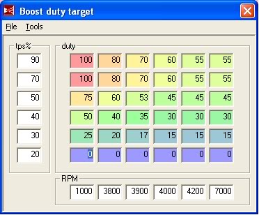
Note that since I have a TPS, I reduced the duty cycles at lower throttle positions to produce more linear throttle response and relieve turbine load at part throttle. This part is optional.
Here's what an open-loop third gear pull looks like:
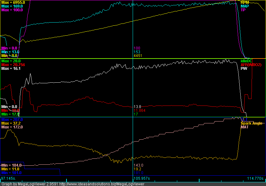
Control is good. You can see the rapid boost ramp from keeping high duty cycles at low RPMs. There is a slight overshoot where EBC starts really controlling around 3900RPM. These is also a slight sag in the middle and a little boost creep at the end. This pull shows boost controlled between 8.5-10psi (average around 9psi). With some more tuning, I'm sure I could get that line straighter.
This pull also illustrates the deficiency in open-loop EBC. The day I tuned it, my average was 10psi. On the day that I logged this pull, it generated 9psi. Open-loop EBC cannot target a boost level. It just sets up physical operating parameters for the valve based upon RPM and TPS. The boost you get depends entirely upon external conditions (atmospheric pressure and temperature, engine compartment heat soak, etc.).
1. Setup the valve parameters;
2. Disable closed loop control; and
3. Tune valve duty cycle targets.
For valve parameters, I bought the DIY EBC valve and just used the defaults. Didn't mess with it. Seems to work.
There are a couple of ways to disable the closed loop control. The MSPNP manual recommends setting all cells of your "Boost kPa Target" table to 70kPa and the "Closed Loop kPa Limit" to 20kPa. Thus, so long as your MAP is at 90kPa or above (as it will be in boost), you will be beyond the "Closed Loop kPa Limits" and operating on the open loop duty cycles.
The other way to disable closed loop control is simply to set 0 as the "Closed Loop kPa Limit." Due to the normal noise on the MAP signal, this condition will never be true except for rare, momentary transitions.
Tuning the valve duty cycles is straightforward. What I did was log a series of third gear pulls with my entire duty cycle table set to a contant value. I would do the third gear pull until I either hit my RPM limit or my boost limit. This was my sequence:
1. Set duty cycle table to 100%. This essentially keeps the EBC valve and wastegate closed.
2. Perform a third gear pull. On this first run, you need to be careful because you are going to hit your boost limit WAY before your RPM limit. This run establishes the lowest RPM at which you can hit your target boost.
3. Set duty cycle to 90%.
4. Perform a third gear pull.
5. Repeat the above while incrementally lowering the duty cycle until you are hitting your RPM limit without hitting your boost limit.
With the above logs, analyze to determine your DC vs. RPM curve for your target boost. My values were:
100%DC -- 3900RPM
90%DC -- 3950RPM
80%DC -- 4000RPM
70%DC -- 4100RPM
60%DC -- 4350RPM
55%DC -- 4400RPM + Held 10psi to Redline
50%DC -- Hit 9psi at 3900RPM and held 9psi to Redline
Armed with the above information, and with the benefit of a few 3rd gear pulls to smooth overshoots and undershoots, I ended up with the following duty cycle target table:
Note that since I have a TPS, I reduced the duty cycles at lower throttle positions to produce more linear throttle response and relieve turbine load at part throttle. This part is optional.
Here's what an open-loop third gear pull looks like:
Control is good. You can see the rapid boost ramp from keeping high duty cycles at low RPMs. There is a slight overshoot where EBC starts really controlling around 3900RPM. These is also a slight sag in the middle and a little boost creep at the end. This pull shows boost controlled between 8.5-10psi (average around 9psi). With some more tuning, I'm sure I could get that line straighter.
This pull also illustrates the deficiency in open-loop EBC. The day I tuned it, my average was 10psi. On the day that I logged this pull, it generated 9psi. Open-loop EBC cannot target a boost level. It just sets up physical operating parameters for the valve based upon RPM and TPS. The boost you get depends entirely upon external conditions (atmospheric pressure and temperature, engine compartment heat soak, etc.).
Reply
2
2
01-09-2012, 07:44 PM
#4
Elite Member
Thread Starter
iTrader: (4)
Join Date: Mar 2008
Location: Granbury, TX
Posts: 6,301
Total Cats: 696
Prerequisites:
1. Before tackling CLEBC, it is assumed that you've setup and tuned Open Loop EBC as discussed above. A well setup OLEBC is critical to getting your CLEBC working correctly. In addition, some of the data that was used to setup OLEBC will be re-used for CLEBC.
2. The other thing that is needed to successfully use CLEBC is a throttle position sensor. Make sure to get one installed and working before attempting this.
The Revelation:
Early on, I "sort of" got CLEBC working just by playing around with the "Proportional Gain" and "Differential Gain" values. However, when starting from low RPM's, I typically got boost overshoots -- which didn't make any sense for a Proportional+Differential control algorithm. This was a typical pattern:
Notice the boost overshoot in second gear. You can also see that the boost control solenoid duty cycle goes to near 100% and then suddenly drops down when this happens (logged as "BCDuty3").
So, I dug into the code and found that the MS-1 uses an Integral+Derivative control loop for CLEBC. There is no proportional term at all. The algorithm is:
Duty Cycle(new) = Duty Cycle(old) + "Proportional Gain" x ( kPa Target - kPa ) - "Differential Gain" x ( kPa(current) - kPa(previous) )
if Duty Cycle(new) > 100% then Duty Cycle(new) = 100%
if Duty Cycle(new) < 0% then Duty Cycle(new) = 0%
What this means is that the algorithm is prone to integral windup, and it is up to us to ensure that integral windup doesn't happen.
Integral Windup:
I know what you're thinking. "OK, Mr. Smarty Pants, what the heck is 'integral windup'?"
Well, I'm older than most of you. Contributing to my advanced age are two daughters, one who is grown and married and almost completely returned by the aliens, and another who has recently been taken by those same aliens (she's 15). In my mind, the best way to explain integral windup is with an analogy to a teenage daughter. Here's an example of the daily fight between my wife and my teenage daughter:
Wife: "Clean your room" or "Do your homework" or "Get off the computer" or (fill in the blank).
Daughter: (Assuming she responds at all) "Yeah, whatever . . ."
Wife (more loudly): "Clean your room" or "Do your homework" or "Get off the computer" or (fill in the blank).
Daughter: (Same response)
Wife (even more loudly): "Clean your room" or "Do your homework" or "Get off the computer" or (fill in the blank).
Daughter: (Same response)
. . . and so on.
In the end, my poor wife has made continuous control inputs into a system (a teenage daughter) that is fundamentally not controllable. The desired system response is not achieved. However, my wife gets totally wound up and pissed off -- which then affects my life negatively. This, my friends, is integral windup.
What does the above have to do with CLEBC? Plenty. There are regions where boost does not (cannot) respond to EBC valve duty cycle changes. If we are in one of these regions and attempt to perform CLEBC with an integral+derivative algorithm, the only thing that will happen is that the EBC valve duty cycle will get wound up and pissed off -- it will rise to 100% or fall to 0% (thankfully, it is limited to these values). Despite this, the target boost will not be achieved. And, once we get into a region where the system is responsive, the CLEBC algorithm will have a lousy starting point and a much more difficult problem to solve -- leading to boost overshoots and undershoots.
There are two regions where this happens:
1. When the throttle isn't open. Megasquirt uses MAP as an indication of boost. MAP, by definition, is sourced AFTER the throttle. As we all know, the throttle is the primary and most powerful control for MAP. If you are trying to control boost (i.e., MAP) with EBC valve duty cycle and the throttle is closed or partially closed, you are wasting your time.
2. Before the turbo spools up. If the engine isn't in an RPM region where the turbo can generate boost, you can be at 100% EBC valve duty cycle all day long and boost won't rise at all.
So, How Can We Use CLEBC and Avoid Integral Windup?
Elementary. Use a hybrid of OLEBC and CLEBC. CLEBC is used in the regions where boost (i.e., MAP) is responsive to EBC valve duty cycle. OLEBC is used everywhere else. This is why it is critical that OLEBC be tuned first.
Looking at the EBC controls, there is a parameter called "Closed Loop kPa Limit (kPa)."
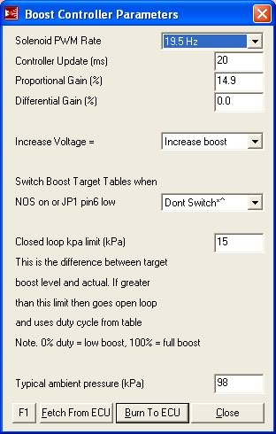
This parameter is intended to be a safety that forces use of OLEBC when it is apparent that CLEBC is not working. It does this by comparing currently sensed boost to the target boost in the "Boost kPa Target" table. A side effect of this parameter is that, if we are clever with our "Boost kPa Target" table, we can actually control the regions where OLEBC and CLEBC are used.
Here's an example (this is what I'm currently using, BTW):
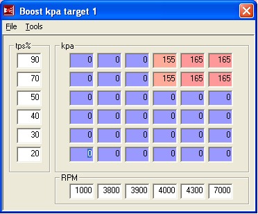
As you can see, I've entered a target of "0" in the areas where I want to use OLEBC, namely at small throttle settings and at low RPMs. Since "0" will naturally fall outside of the "Closed Loop kPa Limit (kPa)", I am forcing OLEBC in those areas. The idea is for OLEBC to handle these transient/uncontrollable regions and give CLEBC a decent starting point at the handoff.
A few implementation details:
1. Determine the minimum RPM for using CLEBC by using the data collected during OLEBC tuning. Basically, with OLEBC set to 100%DC, the lowest RPM where target boost is achieved will be the minimum RPM for CLEBC.
2. Minimum TPS% is set based upon a knowledge of the flow characteristics of butterfly valves (the throttle is such a valve). Basically, by the time you're at 70% throttle, the effect of EBC valve duty cycle will be evident on MAP (assuming you are in the RPM range for boost).
3. Since boost generated by OLEBC depends upon external conditions, the handoff point from OLEBC to CLEBC will also vary. Because of this, you want to set the "Closed Loop kPa Limit (kPa)" to a value that accounts for OLEBC variability. Currently, I'm using 30kPa for this value and it has been working for the temperature extremes I've seen.
4. When setting the "Proportional Gain" and "Differential Gain" values, it helps to plot EBC valve duty cycle. In my installation, this is the "BCDuty3" parameter. What you are shooting for is a curve that expeditiously achieves your boost target without a lot of overshoot or oscillations. I'm currently using a "Proportional Gain" of 20 and a "Differential Gain" of 0.
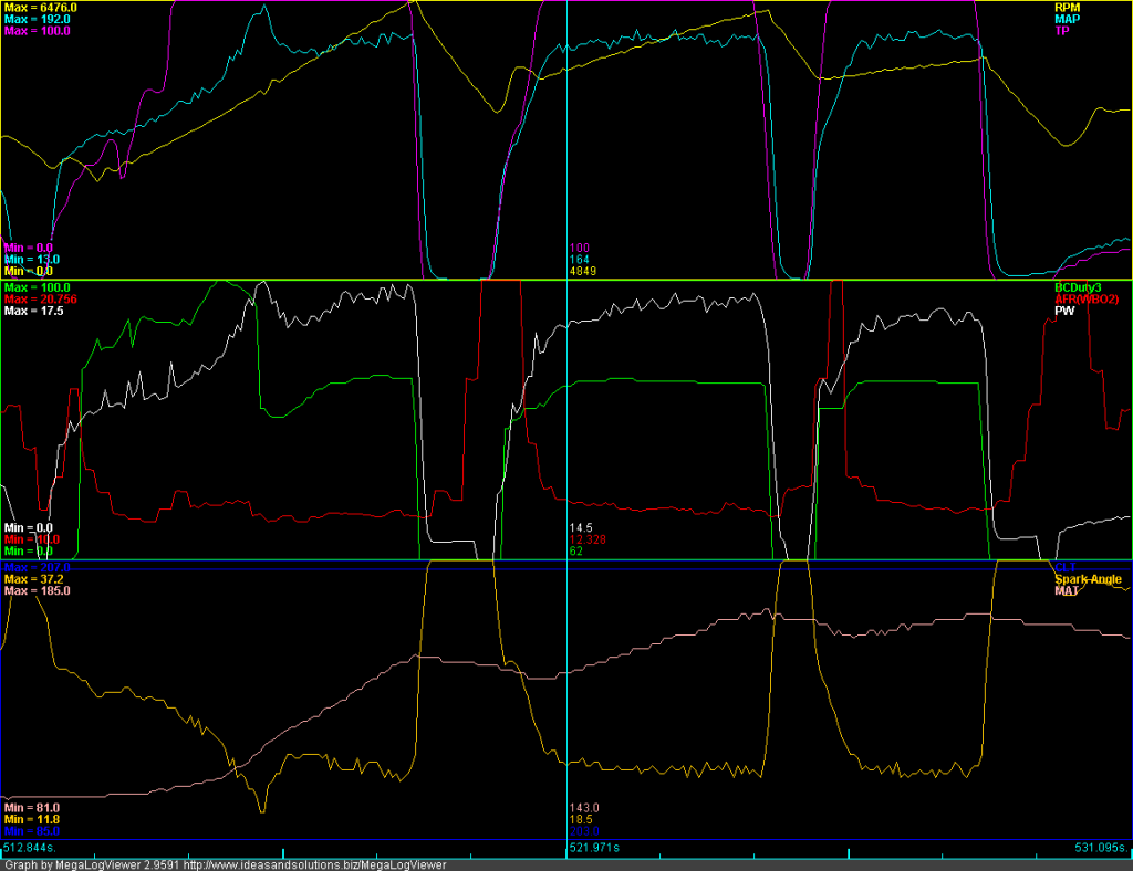
Here are some sample plots:
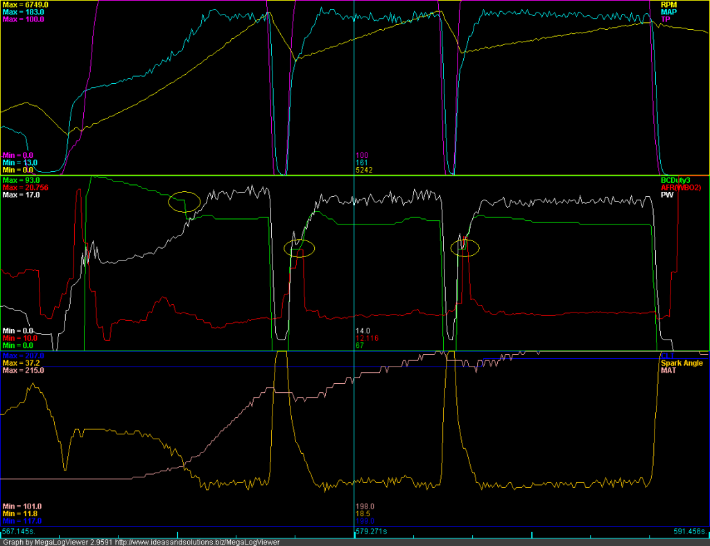
This plot was made on September 13 in some pretty hot conditions (notice minimum MAT is 101 and maximum MAT is 215). I circled the OLEBC to CLEBC handoff points in yellow. You can see that after handoff, the CLEBC seeks its target dynamically. On this particular day, CLEBC was settling to 67%DC.

This plot was made yesterday evening in cool conditions (notice minimum MAT is 64 and maximum MAT is 159). Again, the OLEBC to CLEBC handoff points are circled in yellow. On this particular day, CLEBC was settling to 59%DC. This makes sense. In cooler conditions, it takes less DC to achieve a boost target.
1. Before tackling CLEBC, it is assumed that you've setup and tuned Open Loop EBC as discussed above. A well setup OLEBC is critical to getting your CLEBC working correctly. In addition, some of the data that was used to setup OLEBC will be re-used for CLEBC.
2. The other thing that is needed to successfully use CLEBC is a throttle position sensor. Make sure to get one installed and working before attempting this.
The Revelation:
Early on, I "sort of" got CLEBC working just by playing around with the "Proportional Gain" and "Differential Gain" values. However, when starting from low RPM's, I typically got boost overshoots -- which didn't make any sense for a Proportional+Differential control algorithm. This was a typical pattern:
Notice the boost overshoot in second gear. You can also see that the boost control solenoid duty cycle goes to near 100% and then suddenly drops down when this happens (logged as "BCDuty3").
So, I dug into the code and found that the MS-1 uses an Integral+Derivative control loop for CLEBC. There is no proportional term at all. The algorithm is:
Duty Cycle(new) = Duty Cycle(old) + "Proportional Gain" x ( kPa Target - kPa ) - "Differential Gain" x ( kPa(current) - kPa(previous) )
if Duty Cycle(new) > 100% then Duty Cycle(new) = 100%
if Duty Cycle(new) < 0% then Duty Cycle(new) = 0%
What this means is that the algorithm is prone to integral windup, and it is up to us to ensure that integral windup doesn't happen.
Integral Windup:
I know what you're thinking. "OK, Mr. Smarty Pants, what the heck is 'integral windup'?"
Well, I'm older than most of you. Contributing to my advanced age are two daughters, one who is grown and married and almost completely returned by the aliens, and another who has recently been taken by those same aliens (she's 15). In my mind, the best way to explain integral windup is with an analogy to a teenage daughter. Here's an example of the daily fight between my wife and my teenage daughter:
Wife: "Clean your room" or "Do your homework" or "Get off the computer" or (fill in the blank).
Daughter: (Assuming she responds at all) "Yeah, whatever . . ."
Wife (more loudly): "Clean your room" or "Do your homework" or "Get off the computer" or (fill in the blank).
Daughter: (Same response)
Wife (even more loudly): "Clean your room" or "Do your homework" or "Get off the computer" or (fill in the blank).
Daughter: (Same response)
. . . and so on.
In the end, my poor wife has made continuous control inputs into a system (a teenage daughter) that is fundamentally not controllable. The desired system response is not achieved. However, my wife gets totally wound up and pissed off -- which then affects my life negatively. This, my friends, is integral windup.
What does the above have to do with CLEBC? Plenty. There are regions where boost does not (cannot) respond to EBC valve duty cycle changes. If we are in one of these regions and attempt to perform CLEBC with an integral+derivative algorithm, the only thing that will happen is that the EBC valve duty cycle will get wound up and pissed off -- it will rise to 100% or fall to 0% (thankfully, it is limited to these values). Despite this, the target boost will not be achieved. And, once we get into a region where the system is responsive, the CLEBC algorithm will have a lousy starting point and a much more difficult problem to solve -- leading to boost overshoots and undershoots.
There are two regions where this happens:
1. When the throttle isn't open. Megasquirt uses MAP as an indication of boost. MAP, by definition, is sourced AFTER the throttle. As we all know, the throttle is the primary and most powerful control for MAP. If you are trying to control boost (i.e., MAP) with EBC valve duty cycle and the throttle is closed or partially closed, you are wasting your time.
2. Before the turbo spools up. If the engine isn't in an RPM region where the turbo can generate boost, you can be at 100% EBC valve duty cycle all day long and boost won't rise at all.
So, How Can We Use CLEBC and Avoid Integral Windup?
Elementary. Use a hybrid of OLEBC and CLEBC. CLEBC is used in the regions where boost (i.e., MAP) is responsive to EBC valve duty cycle. OLEBC is used everywhere else. This is why it is critical that OLEBC be tuned first.
Looking at the EBC controls, there is a parameter called "Closed Loop kPa Limit (kPa)."
This parameter is intended to be a safety that forces use of OLEBC when it is apparent that CLEBC is not working. It does this by comparing currently sensed boost to the target boost in the "Boost kPa Target" table. A side effect of this parameter is that, if we are clever with our "Boost kPa Target" table, we can actually control the regions where OLEBC and CLEBC are used.
Here's an example (this is what I'm currently using, BTW):
As you can see, I've entered a target of "0" in the areas where I want to use OLEBC, namely at small throttle settings and at low RPMs. Since "0" will naturally fall outside of the "Closed Loop kPa Limit (kPa)", I am forcing OLEBC in those areas. The idea is for OLEBC to handle these transient/uncontrollable regions and give CLEBC a decent starting point at the handoff.
A few implementation details:
1. Determine the minimum RPM for using CLEBC by using the data collected during OLEBC tuning. Basically, with OLEBC set to 100%DC, the lowest RPM where target boost is achieved will be the minimum RPM for CLEBC.
2. Minimum TPS% is set based upon a knowledge of the flow characteristics of butterfly valves (the throttle is such a valve). Basically, by the time you're at 70% throttle, the effect of EBC valve duty cycle will be evident on MAP (assuming you are in the RPM range for boost).
3. Since boost generated by OLEBC depends upon external conditions, the handoff point from OLEBC to CLEBC will also vary. Because of this, you want to set the "Closed Loop kPa Limit (kPa)" to a value that accounts for OLEBC variability. Currently, I'm using 30kPa for this value and it has been working for the temperature extremes I've seen.
4. When setting the "Proportional Gain" and "Differential Gain" values, it helps to plot EBC valve duty cycle. In my installation, this is the "BCDuty3" parameter. What you are shooting for is a curve that expeditiously achieves your boost target without a lot of overshoot or oscillations. I'm currently using a "Proportional Gain" of 20 and a "Differential Gain" of 0.
Here are some sample plots:
This plot was made on September 13 in some pretty hot conditions (notice minimum MAT is 101 and maximum MAT is 215). I circled the OLEBC to CLEBC handoff points in yellow. You can see that after handoff, the CLEBC seeks its target dynamically. On this particular day, CLEBC was settling to 67%DC.
This plot was made yesterday evening in cool conditions (notice minimum MAT is 64 and maximum MAT is 159). Again, the OLEBC to CLEBC handoff points are circled in yellow. On this particular day, CLEBC was settling to 59%DC. This makes sense. In cooler conditions, it takes less DC to achieve a boost target.
Last edited by hornetball; 01-10-2012 at 09:13 AM.
Reply
2
2
 01-10-2012, 12:49 AM
#7
neither. when you have the stock wastegate hooked up directly and you let of the gas at high rpm you can here the waste gate allowing the exhaust gass to bypass the turbine and go thru the wastegate. since the ms only read pressure from after the throttle butterfly it does not see this excess pressure. So my question is when you close the throttle how does the ebc know to let the wastegate see the excess pressure so the wastegate can allow gas around the turbine. I am afraid this is thread jacking maybe I should start another thread. your thread is great and very informative to a ms newb.
Thanks
Thanks
Reply
0
0
01-10-2012, 09:09 AM
#8
Elite Member
Thread Starter
iTrader: (4)
Join Date: Mar 2008
Location: Granbury, TX
Posts: 6,301
Total Cats: 696
First of all, because the throttle is closed, there is actually little flow through the engine and turbo.
Second, the idea is for a blow-off/recirc valve to open under these conditions to relieve pressure on the compressor and allow the turbo to keep spinning (you actually want the turbo to keep spinning to avoid unnecessary spool time when you get back on it).
If you want to try and keep your wastegate open (to the extent possible) with the throttle closed, then just fill in 0%DC in the bottom row of your "Boost Duty Target" table (as depicted in the Open Loop EBC post above). This will allow the wastegate actuator to see whatever pressure is in your intake tube. Note that under these conditions you are no longer using Closed Loop EBC because you are outside of the CLEBC throttle position range (assuming you've followed the directions above).
Reply
0
0
 01-27-2012, 08:43 AM
#11
Supporting Vendor

Join Date: Sep 2006
Posts: 2,332
Total Cats: 67
Closed loop: You set the amount of boost you want, and the MS adjusts the duty cycle to get this. May take a bit more dialing in to prevent boost spikes or oscillations.
Reply
0
0

Thread
Thread Starter
Forum
Replies
Last Post
Danimal
Miata parts for sale/trade
11
09-29-2007 05:43 AM


