frank's board in a Rev built MS2 +
 07-17-2014, 04:04 PM
#1
Junior Member
Thread Starter
iTrader: (1)

Join Date: Mar 2013
Location: Traverse City, Michigan
Posts: 138
Total Cats: 4
has any one done this?
we are having alt control issues with our MS2 + ( 04 MSM) the noisy alt is freaking out the control chip and shutting down the alternator, i heard franks board may help us has anyone done have pictures of the install and where to solder the wires to on the main board.. my wife wants this car on the road. or i am open to any other options... thank!
we are having alt control issues with our MS2 + ( 04 MSM) the noisy alt is freaking out the control chip and shutting down the alternator, i heard franks board may help us has anyone done have pictures of the install and where to solder the wires to on the main board.. my wife wants this car on the road. or i am open to any other options... thank!
Last edited by ReallyRottenTurbo; 07-17-2014 at 04:05 PM. Reason: help

Reply
 0
0

0
07-17-2014, 04:55 PM
#2

I would suggest getting in contant with reverent and trying to sort this out first, if you haven't already.
As far as the actual electronics though, it shouldn't make a difference. The alternator control board just observes the voltage, and does everything accordingly, requiring no input from megasquirt (unless you choose to wire up the disable wire so it can cut off at low rpm).
I use Frank's board and love it, but there is a good chance that whatever is causing issues with the setup Reverent provides will cause the same issues with Franks.
Reply
0
0
07-17-2014, 05:24 PM
#3

Ask Rev for the correct guide to add a 4.7k resistor and 0.1uF capacitor for your ECU.
That's the guide I got since my repaired/aftermarket PD-alt did not charge at all (MS3-Basic).
Having a internally regulated LS-alt at hand is always helpful. But that also have me not try the fix and see if it helps with my PD-alt (I have three different I can try, a CarGo one, a Hitachi with CarGo electronics and a Mitsubishi), different alts behave a bit different apparently.
Reply
1
1
07-18-2014, 08:33 AM
#4
Senior Member

Join Date: Nov 2007
Location: Belgium
Posts: 999
Total Cats: 73
My board should work perfectly with your MS2+ as it is not actually connected to the megasquirt and it's transistor controlled, not with a programmed chip that can freak out. It just needs ground, power and has a single output to control your alternator and an output to control your low battery light.
There is also an input to disable my board with a general purpose output of the megasquirt, but this input is optional.
There is also an input to disable my board with a general purpose output of the megasquirt, but this input is optional.
Last edited by WestfieldMX5; 07-18-2014 at 01:34 PM.
Reply
0
0
07-18-2014, 09:43 AM
#5
Junior Member
Thread Starter
iTrader: (1)
Join Date: Mar 2013
Location: Traverse City, Michigan
Posts: 138
Total Cats: 4
Thanks everyone for the help I’m just trying to get the car running right I’ve been in contact with Rev but haven’t heard back in about a week and a half now. I know he’s a busy guy he told me he is on vaca and in the process of a move so there is some delay time I have been waiting for exactly this
“Ask Rev for the correct guide to add a 4.7k resistor and 0.1uF capacitor for your ECU.
That's the guide I got since my repaired/aftermarket PD-alt did not charge at all (MS3-Basic)."
He’s supposed to send me photos of one of the ecu’s in his car. And some instructions, but I’m on hold for that. My wife wants her car running and I’m looking at all options to do so. For now the car will charge and then shut down the alt making driving/ tuning no go for now.
"I use Frank's board and love it, but there is a good chance that whatever is causing issues with the setup Reverent provides will cause the same issues with Franks."
from what I’m told the problem is the alt control “chip" that is on the main board for the megasquirt my electrically noisy alt ( stk 04 MSM alt) is over whelming it and making it shut down the alt and all charging... I can on the fly shut down the car and restart and watch the alt charge again for a little while then shut back down when watching the gauge display on tuner studio
Again thanks for the help everyone much appreciated
Reply
0
0
07-23-2014, 01:09 PM
#6
Junior Member
Thread Starter
iTrader: (1)
Join Date: Mar 2013
Location: Traverse City, Michigan
Posts: 138
Total Cats: 4
sorry again for my ignorance but does anyone have photos of this wired in and how they ran the signal wire to the alt? please would be greatly appericated
Reply
0
0
07-24-2014, 12:53 PM
#9
Senior Member
Join Date: Nov 2007
Location: Belgium
Posts: 999
Total Cats: 73
From my site:
The board has 5 pins:
The board has 5 pins:
- 12V
- GND
- Field: this is the output to the alternator field wire (pin 1O on a �99-�00 NB and pin 3U on a �01-�05 NBFL)
- Disable (optional): When you ground this pin, the alternator stops charging.
I use a general purpose output to disable the alternator while I�m cranking (<600rpm) and when tps > 99%. (to gain a tiny bit of hp at full throttle). If this is not desired, leave disconnected. - LowBatt (optional): This output goes to the low battery light (pin 1Q on a �99-�00 NB and pin 3M on a �01-�05 NBFL) and triggers it when voltage goes below 12.8V. If this is not desired, leave disconnected.
Reply
1
1
08-12-2014, 09:52 AM
#11
Junior Member
Thread Starter
iTrader: (1)
Join Date: Mar 2013
Location: Traverse City, Michigan
Posts: 138
Total Cats: 4
any one have photos of how the mounted this in ECU case? its alot smaller than the ecu case so i cant slide it in the ridges in there that holds boards... but i see some extra holes in the ecu board if i buy some bolts spacers and nylon washer i can maybe suspend mount it on the board... just looking for ideas guys thanks!
Reply
0
0
08-13-2014, 09:41 AM
#12
Junior Member
Thread Starter
iTrader: (1)
Join Date: Mar 2013
Location: Traverse City, Michigan
Posts: 138
Total Cats: 4
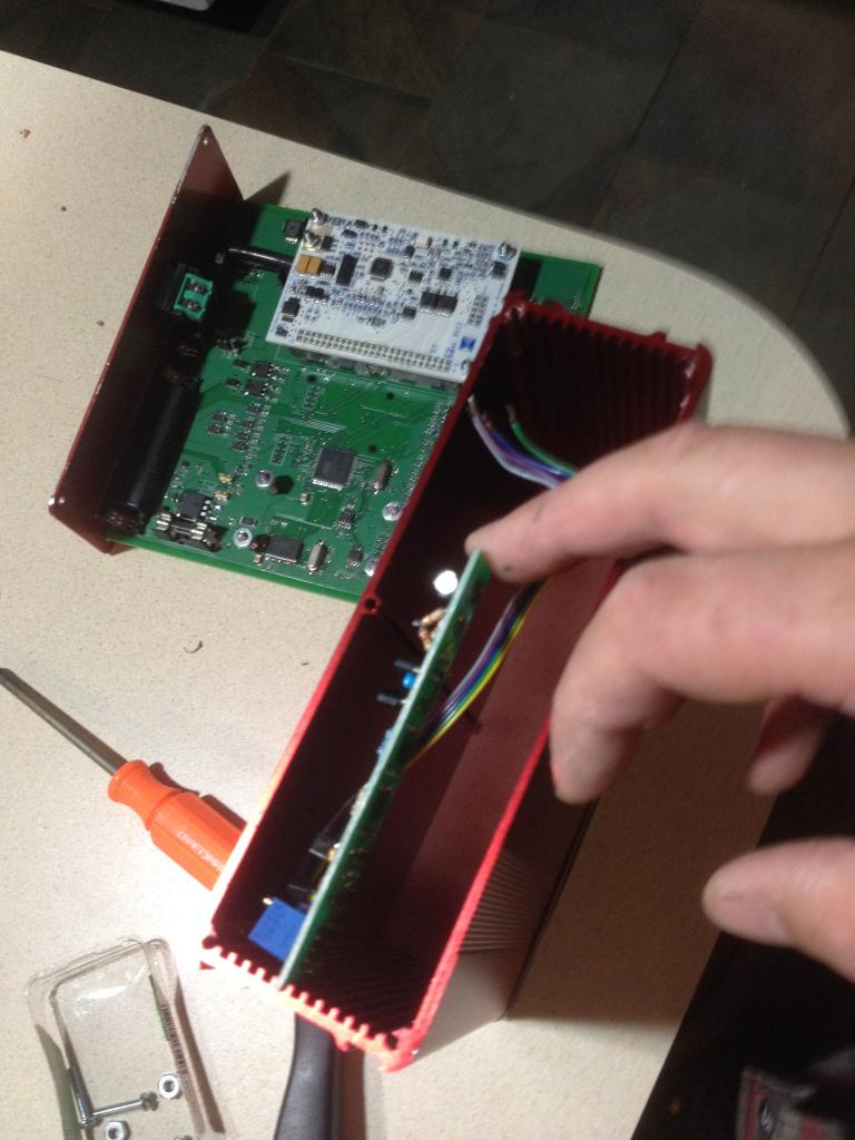
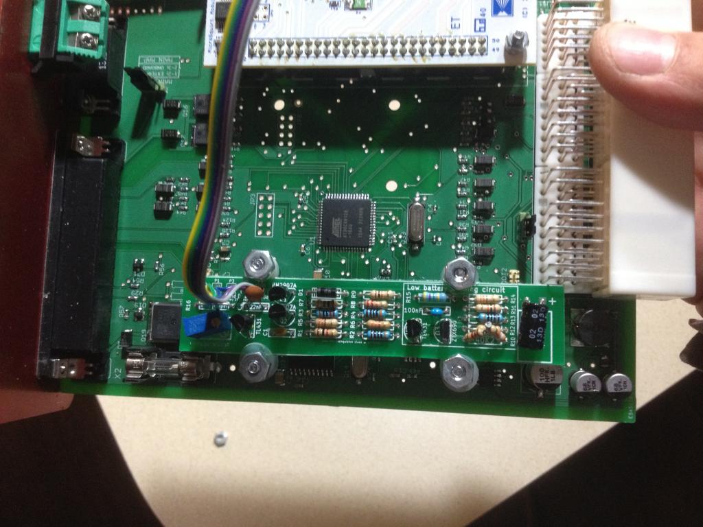
in case its usefull to someone else here is how i mounted the franks board in a rev built MS2+ case. since it cant span the whole case i used existing holes in main board.. nylon washers little screws and nuts worked out pretty good. i ran the wires out side the case and to plugs so i can still fully remove ECU now with out cutting wires.


Reply
0
0
08-13-2014, 01:11 PM
#14
Junior Member
Thread Starter
iTrader: (1)
Join Date: Mar 2013
Location: Traverse City, Michigan
Posts: 138
Total Cats: 4
frank, i didnt know where inside to hook them up to besides the pins off the harness connector but i didnt want to cut those incase of a issue, or selling ecu, ect.. if i had more guidence and knew exactly where they should go. i just dont know enough about to feel safe taping in to pins in the ECU. if you have more info you can share with me via email or photos or can explain where to solder them all to inside the ecu im willing to try. i have no one local to lean on for help
Reply
0
0
08-13-2014, 01:39 PM
#15
Senior Member
Join Date: Nov 2007
Location: Belgium
Posts: 999
Total Cats: 73
I understand. You can solder 3 of the 5 wires to the underside of Rev's board, directly onto the pins of the white connector. This will not interfere with the rest of the system. No idea if there's spare power points, that would even be easier 
12V to pin 4AF (white/red wire in your wiring)
GND to pin 4A (black/blue)
Low batt light to pin 3U (brown/red)
The disable wire needs to go to an unused spare output. I have no idea how Rev wires these, but I'm sure he can tell you were to connect inside the ecu.
The field output normally goes to pin 3M (gray/red), again inside the case, but if you don't want to cut Rev's original circuit, you'll have to bring it out the case, yes. But this is the only wire that will need to be brought out of the case.
Reply
1
1
08-13-2014, 02:22 PM
#16
Junior Member
Thread Starter
iTrader: (1)
Join Date: Mar 2013
Location: Traverse City, Michigan
Posts: 138
Total Cats: 4
Thanks frank !! very helpful!!
that sounds alot cleaner install
just to double check before i do this when i get home tonight i have a few questions
those pin locations are correct for a 04 MSM harness?
12V to pin 4AF (white/red wire in your wiring)
GND to pin 4A (black/blue)
Low batt light to pin 3U (brown/red)
isnt the disable wire optional or do i need to have that wired up?
and yes the 3M pin i would want to run outside so i dont have to cut one of his ECU pins inside.
thank you !!
I understand. You can solder 3 of the 5 wires to the underside of Rev's board, directly onto the pins of the white connector. This will not interfere with the rest of the system. No idea if there's spare power points, that would even be easier
12V to pin 4AF (white/red wire in your wiring)
GND to pin 4A (black/blue)
Low batt light to pin 3U (brown/red)
The disable wire needs to go to an unused spare output. I have no idea how Rev wires these, but I'm sure he can tell you were to connect inside the ecu.
The field output normally goes to pin 3M (gray/red), again inside the case, but if you don't want to cut Rev's original circuit, you'll have to bring it out the case, yes. But this is the only wire that will need to be brought out of the case.
Reply
0
0
08-14-2014, 12:35 PM
#19
Junior Member
Thread Starter
iTrader: (1)
Join Date: Mar 2013
Location: Traverse City, Michigan
Posts: 138
Total Cats: 4
frank,
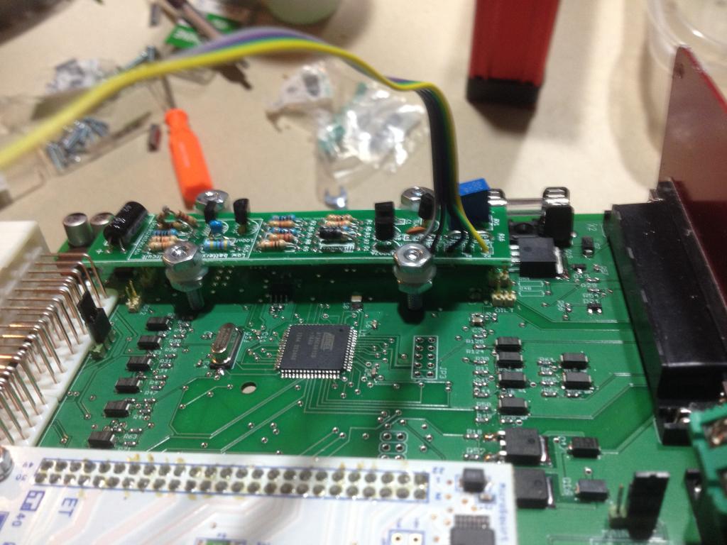
i went back in and lightly soldered 3 wires to the bottom side of main board for the white ECU plugs
12v source to 4AF
ground to 4A
low battery light to 3U
and awaiting word from REV via email in regards to the feild wire 3M if i should tap in to ECU or just run outside case and clip wire after ECU plug ...
Reply
0
0


