Pre-Install Checklist for DIYPNP
 05-22-2015, 12:07 AM
#1
Junior Member
Thread Starter

Join Date: Feb 2015
Posts: 142
Total Cats: 6
Hey guys, I finished soldering my DIYPNP box a few weeks ago and I'm planning on installing it this weekend. To putting together a checklist and I'm hoping those who have done it before can review to make sure I'm not leaving anything out. A little info about my setup:
- Car is 1995
- Stock other than 2.5" exhaust starting at the cat
- A/C + Cruise (not sure if that matters)
- DIYPNP w/ sequential module
- IAT sensor with suggestions on where to put it.
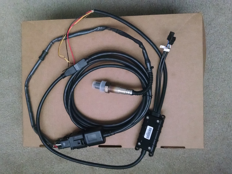
- LC-2 wideband
- Bench tested on MacBook
- I've flashed to the latest version of firmware (ver 3.3.3) and loaded the 3.3.1a basemap file from here. When I loaded the file, it threw several errors, presumably because the firmware versions don't match. Should I be concerned? Does anyone have a basemap for the latest f/w?
- As far as location for the controller, I've seen guys put the unit in front of the shift boot, beneath the shift console, as well as attached to the metal frame under the dash. What's the general consensus on best placement?
- Wiring, starting with hot. Official documentation suggests adding a relay to the battery with a 5A inline fuse. Did you go this route? Did you find a good spot for the relay? I've also seen the factory EFI fuel pump relay or window switch used. Any reason not to do this?
- Ground - Negative battery post recommended. Also recommended is to share ground with the ECU. Did you ground this way? If so, what was the order? Use the post and then may a Y to the ECU and LC-2? Or daisy chain in a specific order?
- Yellow - To ECU
- Brown - To AFR gauge? I don't have one. Do I need one?
- Serial In & Out - I don't use these for my set up, correct?
- I have a set of freshly flowed 550cc injectors, but I've read its best to figure out tuning on stock first and throw them in once I get that nailed down. Is that what you would recommend?
- Anything else I should know that you wish you would have known when you swapped your ECU??

Reply
 0
0

0
05-22-2015, 07:19 AM
#2
Senior Member

Join Date: Apr 2011
Location: Hollywood, FL
Posts: 807
Total Cats: 163
1. Ignore the errors, accept whatever it wants you to accept, change all settings to match what you are using. You now have a 3.3.3 base map.
2. WB controller outside in engine bay zip tied to brake lines. Sensor cable doesnt reach inside unless you make a new hole by trans tunnel?
3, 4, 5, 6, 7. Do exactly as the instructions say and well you need serial in order to comm with controller so what do you think?
8. Makes no difference but eliminates a variable. Make sure the info is correct for injectors, all of the info.
9. If you have a 95.5 the tach wire is in a different spot on the harness
Reply
0
0
05-22-2015, 07:55 AM
#3
Boost Czar


iTrader: (62)
Join Date: May 2005
Location: Chantilly, VA
Posts: 79,488
Total Cats: 4,077
1. I have a 3.3.3 seq. basemap i could send.
But I wire mine a particular way that differs slightly from the DIY docs.
I bring the a/c switch into PE1 and the output is on WLD or ALD (cant remember off my head). That way the MS controls the a/c compressor and you have the true idle-up delay for seamless activation.
2. Mine sat beneath my stereo and the sensor went down through the shift boot. Wire your DIYPNP to bring 12v and GND to the DB15 as well as the Wbo2 input--wire your LC2 back to the DB15. I suggest an inline fuse on the power wire.
3. no. see #2
4. no. see #2
5. yes.
6-7. eh.
8. up to you. 10minutes to swap, so might as well get running on stock injectors, then swap the new ones in to eliminate any variables.
9. make sure you sync the timing, and then go back to "use table".
Reply
0
0
05-22-2015, 10:27 AM
#4
Junior Member
Thread Starter
Join Date: Feb 2015
Posts: 142
Total Cats: 6
Warning: Noob questions to follow. 
That might be helpful.
So just to review the A/C switch input is 1Q and is going to both 1J and 4S (like the manual). Do you take 1Q to PE1 in addition to 1J and 4S or in place of 1J and 4S?
If I understand this correctly the DB15 serves as an output to the LC-2 and the MS gets its power from the huge factory ECU connector in the back.
2a. Is there a pinout standard for the DB15, or do I simply choose any 3 pins?
2b, Inside the MS, I run a wire from each of the 3 DB15 pins to 12v, ground, and O2 signal (4N on the adapter) respectively. Right?
2c. The inline fuse would be here: MS --> DB15 --> 5A fuse --> LC-2. Like that?
Honestly, I thought the yellow wire addressed that. Where do the (2) 4-pin connectors go? I was under the impression the OUT was used for loading firmware updates and changing defaults. Where does the IN go?
Noted.
That might be helpful.
2a. Is there a pinout standard for the DB15, or do I simply choose any 3 pins?
2b, Inside the MS, I run a wire from each of the 3 DB15 pins to 12v, ground, and O2 signal (4N on the adapter) respectively. Right?
2c. The inline fuse would be here: MS --> DB15 --> 5A fuse --> LC-2. Like that?
Noted.
Reply
0
0
05-23-2015, 12:52 AM
#5
Junior Member
Thread Starter
Join Date: Feb 2015
Posts: 142
Total Cats: 6
1a. I came across an old post from Brain explaining the A/C wiring.
To recap, my current setup is:
Implementing Brain's method would involve:
Or do you skip the RELAY altogether, like this:
To recap, my current setup is:
- Omitted R14
- Relay 1 IN --> PA0
- Relay 1 OUT --> IL (radiator fan)
- Input 1 IN --> 1Q (A/C switch)
- Input 1 OUT --> 1J, 4S (?,?)
Implementing Brain's method would involve:
- Re-installing R14 (2.2k)
- Relay 1 IN --> WLED
- Relay 1 OUT --> No change, 1L
- Input 1 IN --> No change, 1Q
- Input 1 OUT --> PE1
- PA0 (or optionally ALED) --> 1J, 4S
Or do you skip the RELAY altogether, like this:
- WLED --> 1L
- Input in --> 1Q
- Input 1 out --> PE1
- PAO --> IJ, 4S
Last edited by Windows95; 05-23-2015 at 03:24 PM.
Reply
0
0
05-23-2015, 07:18 AM
#6
Senior Member
Join Date: Apr 2011
Location: Hollywood, FL
Posts: 807
Total Cats: 163
No, that is a signal wire. There are no "comms" on that wire.
These are your comm connections as you noted above. Read the instructions.
Where do the (2) 4-pin connectors go? I was under the impression the OUT was used for loading firmware updates and changing defaults. Where does the IN go?
Reply
0
0
05-23-2015, 09:54 AM
#7
Junior Member
Thread Starter
Join Date: Feb 2015
Posts: 142
Total Cats: 6
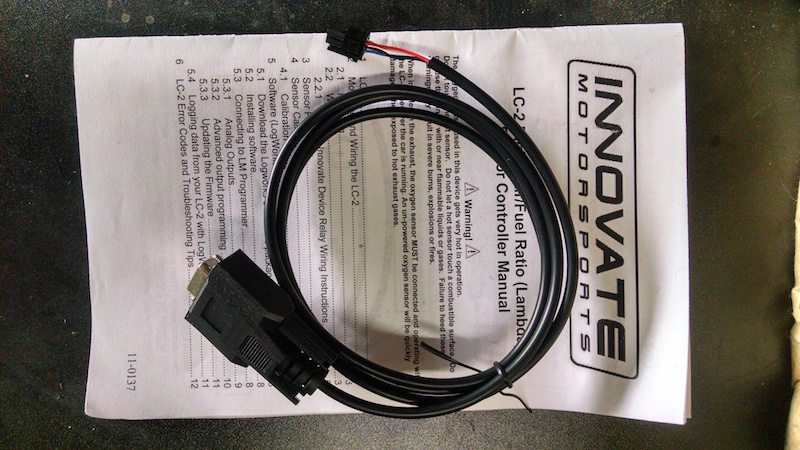
The LC-2�s serial connectors are utilized when needed to program analog output settings, data log via the Logworks software with a Windows PC, or to daisy chain with other Innovate Motorsports� devices.
Reply
0
0
05-23-2015, 10:06 AM
#8
Senior Member
Join Date: Apr 2011
Location: Hollywood, FL
Posts: 807
Total Cats: 163
I think you are looking at the quick start guide. You need to look at the manual. Specifically section 5.
http://www.innovatemotorsports.com/s...C-2_Manual.pdf
It should include a serial cable but its a 2.5mm? jack to rs232 so its not useful for new machines unless you have a rs232 to usb adapter which I'm sure you have since you have a DIYPNP which doesn't have native USB.
On mine I had to communicate with the controller once since I needed two 0-5V wideband outputs and my LC1 came configured for one 0-5V wideband output and one 0-1V simulated narrow band output. One output was for the display gauge and the other to go straight into the DIYPNP.
Edit: The LC1 has 2.5mm serial connector while the LC2 has different connectors. Either way you need to adapt these to your PC to be able to comm with the controller. Likely you only need to do it once but.... you aren't using a gauge.
Last edited by hector; 05-23-2015 at 10:26 AM.
Reply
1
1
05-23-2015, 10:51 AM
#9
Junior Member
Thread Starter
Join Date: Feb 2015
Posts: 142
Total Cats: 6
I think you are looking at the quick start guide. You need to look at the manual. Specifically section 5.
http://www.innovatemotorsports.com/s...C-2_Manual.pdf
http://www.innovatemotorsports.com/s...C-2_Manual.pdf
Sounds like one solution would involve making a 4-pin to rs232 adapter. Then I could use the serial to USB cable I already have to comm with my laptop.
Reply
0
0
 05-23-2015, 12:08 PM
#12
Senior Member
Join Date: Apr 2011
Location: Hollywood, FL
Posts: 807
Total Cats: 163
Yeah you are missing the serial comm cable. Unless this was some kind of packaging that didn't come with it for some reason. Shoot them an email. Might have to wit til tuesday for a response.
Reply
0
0
05-23-2015, 12:48 PM
#13
Junior Member
Thread Starter
Join Date: Feb 2015
Posts: 142
Total Cats: 6

Thanks for helping me realize I needed to track it down. So...to take it full circle, after programming via PC, I won't need the Serial IN/OUT unless I have a gauge.
Reply
0
0
05-23-2015, 01:06 PM
#14
Senior Member
Join Date: Apr 2011
Location: Hollywood, FL
Posts: 807
Total Cats: 163
Actually since you only need one 0-5V signal (which you currently have available via the yellow wire) you don't need to comm with the controller at all. It should work as is.
Now if you want to confirm you have the latest software, etc. then go ahead. Or if you get a display gauge that works on 0-5V or even some other voltage requirement.
Note that some people have needed to fine tune the reading in the Tunerstudio gauge to read the same voltage as reported by a display gauge. Generally it's off by .2-.3 AFR. So maybe hook up to the controller and confirm you are getting the same readings from the controller in TS. If not, adjust TS WBo2 settings in "Tools" "calibrate AFR" or something like that.
Reply
0
0
05-23-2015, 10:50 PM
#16
Boost Czar
iTrader: (62)
Join Date: May 2005
Location: Chantilly, VA
Posts: 79,488
Total Cats: 4,077
<p>WLED - 1L</p><p>ALED - 1J, 4S</p><p>Input 1 IN - 1Q </p><p>INput 1 OUT - PE1</p><p>Input 2 IN - 1V</p><p>Input 2 OUT - FLEX</p><p>PAO - Boost IN</p><p>Boost OUT - DB15 pin</p><p> </p><p>need to put the 2.2K resistor on R14 back.</p><p> </p><p> </p>
Last edited by Braineack; 05-26-2015 at 07:26 AM.
Reply
0
0

Thread
Thread Starter
Forum
Replies
Last Post
Mikel
MEGAsquirt
4
09-28-2015 04:46 PM


