MS3x Questions


 08-24-2013, 04:42 PM
#26
I'm a terrible person

Thread Starter
iTrader: (19)
Join Date: Apr 2009
Location: Arizona
Posts: 7,174
Total Cats: 180
So I'm going to omit U6 and the c26-29 since I wont' be using the serial port at all. Hopefully this b works. Almost done. WIll find out how much I fail today.

Reply
 0
0

0
08-24-2013, 05:18 PM
#28
I'm a terrible person
Thread Starter
iTrader: (19)
Join Date: Apr 2009
Location: Arizona
Posts: 7,174
Total Cats: 180
I haven't looked to find one. I'd imagine I will have trouble finding something for 1200cc injectors, dw300 and stock 1.6. But can probably adjust it enough to atleast get it started and tuning. Trying to figure out how to use this Jimstim for now, and figuring out what you mean by this syncing I need to do.
Last edited by FRT_Fun; 08-24-2013 at 05:29 PM.
Reply
0
0
08-24-2013, 05:35 PM
#29
I'm a terrible person
Thread Starter
iTrader: (19)
Join Date: Apr 2009
Location: Arizona
Posts: 7,174
Total Cats: 180
Okay it detected the MS3 over USB and says it has firmware 1.2 on it already. I guess the current is 1.2.3? It's flashing to that now. So far so good................
Uh also holy **** the westfield site is no more? Welp glad I just about finished this MS3x.
Also I'm using this for my msq: https://www.miataturbo.net/megasquir...-signal-69409/
A lot of errors since the firmware was older, so I still have to go through and set everything up for the most part.
Uh also holy **** the westfield site is no more? Welp glad I just about finished this MS3x.
Also I'm using this for my msq: https://www.miataturbo.net/megasquir...-signal-69409/
A lot of errors since the firmware was older, so I still have to go through and set everything up for the most part.
Last edited by FRT_Fun; 08-24-2013 at 06:37 PM.
Reply
0
0
08-24-2013, 07:09 PM
#30
I'm a terrible person
Thread Starter
iTrader: (19)
Join Date: Apr 2009
Location: Arizona
Posts: 7,174
Total Cats: 180
Okay I have a red box on the bottom of TunerStudio that says "Not Ready" and no tach.
I have JP7 jumped, and 2.39v from the 2 pots, and 2&3 on the DIP switch are on.
What do?
Okay noticed that on the StimX injector A-D will flash in sequence once, and then Injector G LED stays lit. The Idle LED is also lit.
I have JP7 jumped, and 2.39v from the 2 pots, and 2&3 on the DIP switch are on.
What do?
Okay noticed that on the StimX injector A-D will flash in sequence once, and then Injector G LED stays lit. The Idle LED is also lit.
Last edited by FRT_Fun; 08-24-2013 at 07:41 PM.
Reply
0
0
08-24-2013, 09:52 PM
#31
I'm a terrible person
Thread Starter
iTrader: (19)
Join Date: Apr 2009
Location: Arizona
Posts: 7,174
Total Cats: 180
Okay small update. After removing the JP8 (it said it didn't matter if it was used or not, it came with it installed so I left it) the IGN G LED does not come on.
When I power on the JimStim INJ A-D flash in sequence and then nothing.
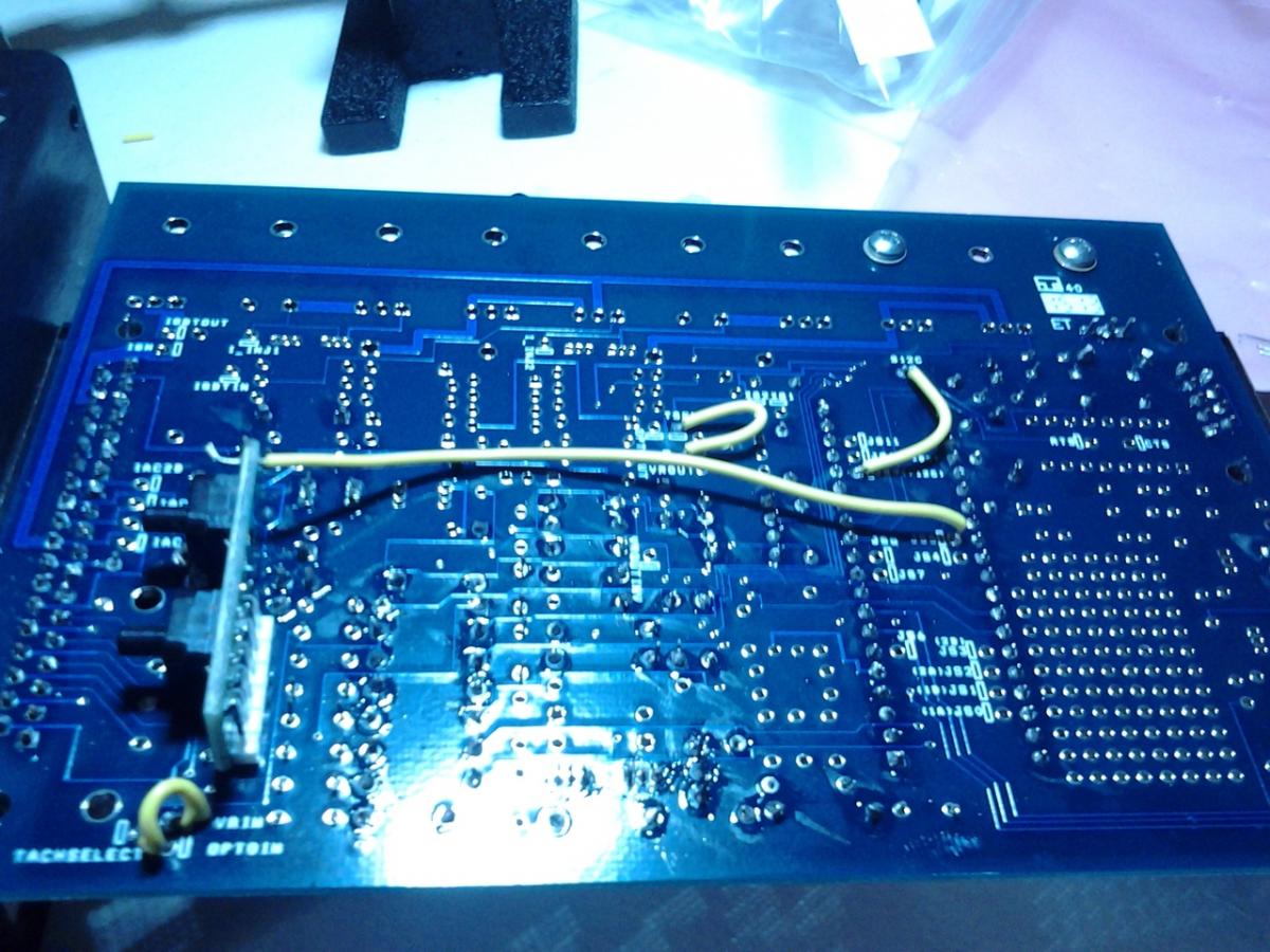
Not sure if anyone saw my question about q22/q23... but if I overheated those while soldering would this cause my issue? Or if there was a bridge? Those legs were so close it's hard to tell if solder is shorting the legs.
When I power on the JimStim INJ A-D flash in sequence and then nothing.
Not sure if anyone saw my question about q22/q23... but if I overheated those while soldering would this cause my issue? Or if there was a bridge? Those legs were so close it's hard to tell if solder is shorting the legs.
Last edited by FRT_Fun; 08-24-2013 at 10:15 PM.
Reply
0
0
08-25-2013, 05:39 PM
#33
I'm a terrible person
Thread Starter
iTrader: (19)
Join Date: Apr 2009
Location: Arizona
Posts: 7,174
Total Cats: 180
I'm back. So for my CAS... where do I wire those wires in to the MS? I am building a harness from scratch so I'm not just plugging in my stock wiring harness. I see the expander has a CAM input and the MS has an input as well.
I'm about to check out and see if it's clear on the wiring diagram which goes where. But if anyone just wants to save me some time and tell me what color wires go to which pin on the MS and expander I will be happy.
I'm about to check out and see if it's clear on the wiring diagram which goes where. But if anyone just wants to save me some time and tell me what color wires go to which pin on the MS and expander I will be happy.
Reply
0
0
08-25-2013, 08:57 PM
#35
I'm a terrible person
Thread Starter
iTrader: (19)
Join Date: Apr 2009
Location: Arizona
Posts: 7,174
Total Cats: 180
I understood which pins for the MS the cam and crank go to. But since they both come from the CAS I was unsure of which of the 4 wires went to which pins. I see from the MS3x 90-93 1.6 harness wiring diagram of yours its:
Y/L - Pin 32 Cam IN - MS3x
W - Pin 24 Crank IN - MS mainboard (for some reason it says pin 25 on yours but the diagram shows pin 24)
B - Pin 1 Ground
Then:
W/R - Main Relay
Y/L - Pin 32 Cam IN - MS3x
W - Pin 24 Crank IN - MS mainboard (for some reason it says pin 25 on yours but the diagram shows pin 24)
B - Pin 1 Ground
Then:
W/R - Main Relay
Reply
0
0


