MS3x Questions
 08-16-2013, 01:22 AM
#1
I'm a terrible person

Thread Starter
iTrader: (19)
Join Date: Apr 2009
Location: Arizona
Posts: 7,174
Total Cats: 180
I'm following: 90-97 MS3 | Frank's Westfield MX5 90-97 MS3 |
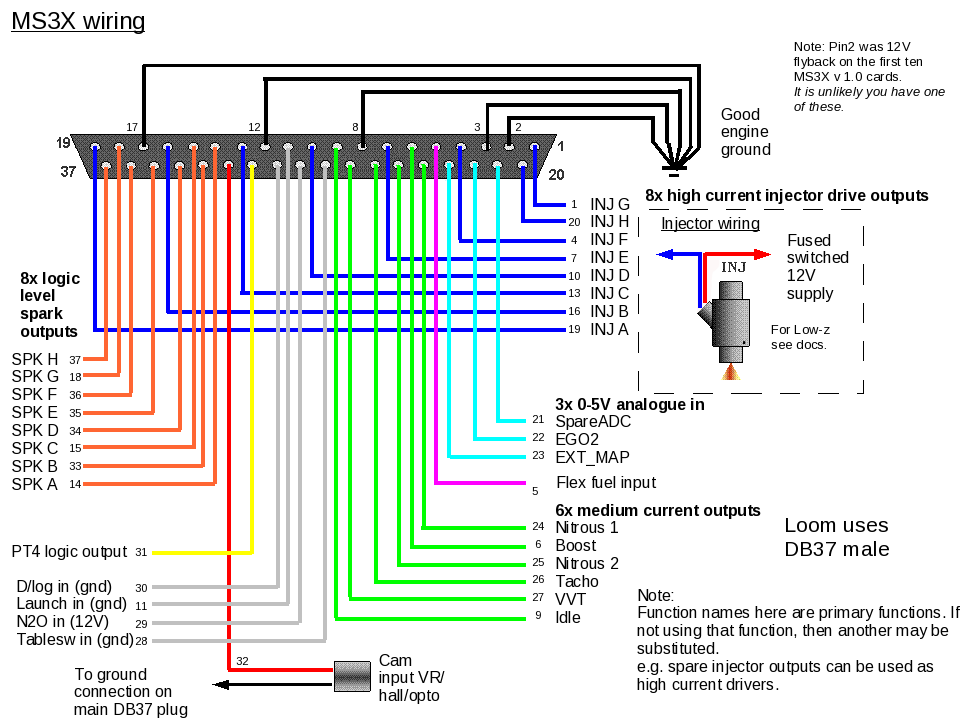
But my setup is a tiny bit different so I wanted to clarify some things. (pin corresponds to the diagram below)
1. I plan to run full sequential, injectors and ignition. I have 4 ignitors that will use 4 spark outputs on the expansion. Do I use a tach output from the expansion to the gauge cluster for my gauge tach? Is that Pin 26 on the expansion?
2. Pin 30 can go to a switch, which then goes to ground which will allow data logging when the switch is grounded?
3. Found answer.
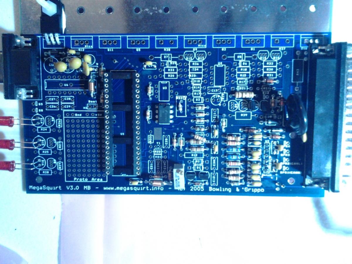
4. In the MS3 assembly in the link above, this:
Step 9: jumpers
- jumper S12C to JS9
- jumper TACHSELECT to VRIN
- jumper VROUT to TSEL
is just a wire going from each of these locations ON the actual MS3?
5. And same as above, this:
Part 3: Wiring
Step 1: flyback diodes
Install a 1N4001 with the banded side to 12V and the other side to the idle output of the MS3X (pin 9).
Install a 1N4001 with the banded side to 12V and the other side to the fan output of the MS3X (pin 1).
Install a 1N4001 with the banded side to 12V and the other side to the a/c fan output of the MS3X (pin ).
Is done on the actual harness NOT the ms3x? Also the fan output says pin 1... that is INJ G on the MS3x... Am I missing something here? Also I'm not using a/c, so I'm going to say there is no reason to install the 1N4001 for that?
Also one last thing... The transistors were a pain with the leads being so close. I had to repair some solder that jumped leads and the transistor got quite hot in the process. Should I be worried? I didn't apply heat for more than 5-6 seconds before letting it cool down. But it was def too hot to touch for a second or two.
But my setup is a tiny bit different so I wanted to clarify some things. (pin corresponds to the diagram below)
1. I plan to run full sequential, injectors and ignition. I have 4 ignitors that will use 4 spark outputs on the expansion. Do I use a tach output from the expansion to the gauge cluster for my gauge tach? Is that Pin 26 on the expansion?
2. Pin 30 can go to a switch, which then goes to ground which will allow data logging when the switch is grounded?
3. Found answer.
4. In the MS3 assembly in the link above, this:
Step 9: jumpers
- jumper S12C to JS9
- jumper TACHSELECT to VRIN
- jumper VROUT to TSEL
is just a wire going from each of these locations ON the actual MS3?
5. And same as above, this:
Part 3: Wiring
Step 1: flyback diodes
Install a 1N4001 with the banded side to 12V and the other side to the idle output of the MS3X (pin 9).
Install a 1N4001 with the banded side to 12V and the other side to the fan output of the MS3X (pin 1).
Install a 1N4001 with the banded side to 12V and the other side to the a/c fan output of the MS3X (pin ).
Is done on the actual harness NOT the ms3x? Also the fan output says pin 1... that is INJ G on the MS3x... Am I missing something here? Also I'm not using a/c, so I'm going to say there is no reason to install the 1N4001 for that?
Also one last thing... The transistors were a pain with the leads being so close. I had to repair some solder that jumped leads and the transistor got quite hot in the process. Should I be worried? I didn't apply heat for more than 5-6 seconds before letting it cool down. But it was def too hot to touch for a second or two.
Last edited by FRT_Fun; 08-16-2013 at 02:12 AM.

Reply
 0
0

0
08-16-2013, 03:43 AM
#2
Senior Member

Join Date: Nov 2007
Location: Belgium
Posts: 999
Total Cats: 73
1. depends if your ignitors have a tach signal or not. If not (likely), use the MS tach output to drive your gauge.
2. yes, if you use that pin in the TunerStudio settings
3. great
4. yes, see pictures in my writeup
5. doesn't matter but I do it in the harness (actually on the connector) and not always on the pcb. The reason being that flyback currents can be high and it's not uncommon that they burn out a trace on the pcb. Thus play safe and do it on something that can handle high current (wiring / connector)
I'm using inj G as the fan output in my particular setup (and in the msq provided on my site). You may choose any free pin that you like (and can deliver at least 500mA).
Reply
0
0
08-16-2013, 11:13 AM
#3
I'm a terrible person
Thread Starter
iTrader: (19)
Join Date: Apr 2009
Location: Arizona
Posts: 7,174
Total Cats: 180
1. depends if your ignitors have a tach signal or not. If not (likely), use the MS tach output to drive your gauge.
2. yes, if you use that pin in the TunerStudio settings
3. great
4. yes, see pictures in my writeup
5. doesn't matter but I do it in the harness (actually on the connector) and not always on the pcb. The reason being that flyback currents can be high and it's not uncommon that they burn out a trace on the pcb. Thus play safe and do it on something that can handle high current (wiring / connector)
I'm using inj G as the fan output in my particular setup (and in the msq provided on my site). You may choose any free pin that you like (and can deliver at least 500mA).
2. yes, if you use that pin in the TunerStudio settings
3. great
4. yes, see pictures in my writeup
5. doesn't matter but I do it in the harness (actually on the connector) and not always on the pcb. The reason being that flyback currents can be high and it's not uncommon that they burn out a trace on the pcb. Thus play safe and do it on something that can handle high current (wiring / connector)
I'm using inj G as the fan output in my particular setup (and in the msq provided on my site). You may choose any free pin that you like (and can deliver at least 500mA).
Thank you. Your website has been a life saver. You rock.

Reply
0
0
08-17-2013, 01:20 AM
#4
I'm a terrible person
Thread Starter
iTrader: (19)
Join Date: Apr 2009
Location: Arizona
Posts: 7,174
Total Cats: 180
Can I assume:
- C1, C3, C18, C19, C239 (0.1�F)
Is C23 and C29?
Don't see 29 on the layout, so I guess just 23.
- C1, C3, C18, C19, C239 (0.1�F)
Is C23 and C29?
Don't see 29 on the layout, so I guess just 23.
Last edited by FRT_Fun; 08-17-2013 at 01:30 AM.
Reply
0
0
08-21-2013, 12:55 AM
#7
I'm a terrible person
Thread Starter
iTrader: (19)
Join Date: Apr 2009
Location: Arizona
Posts: 7,174
Total Cats: 180
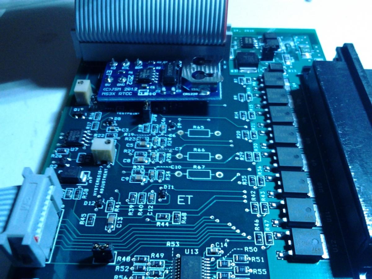
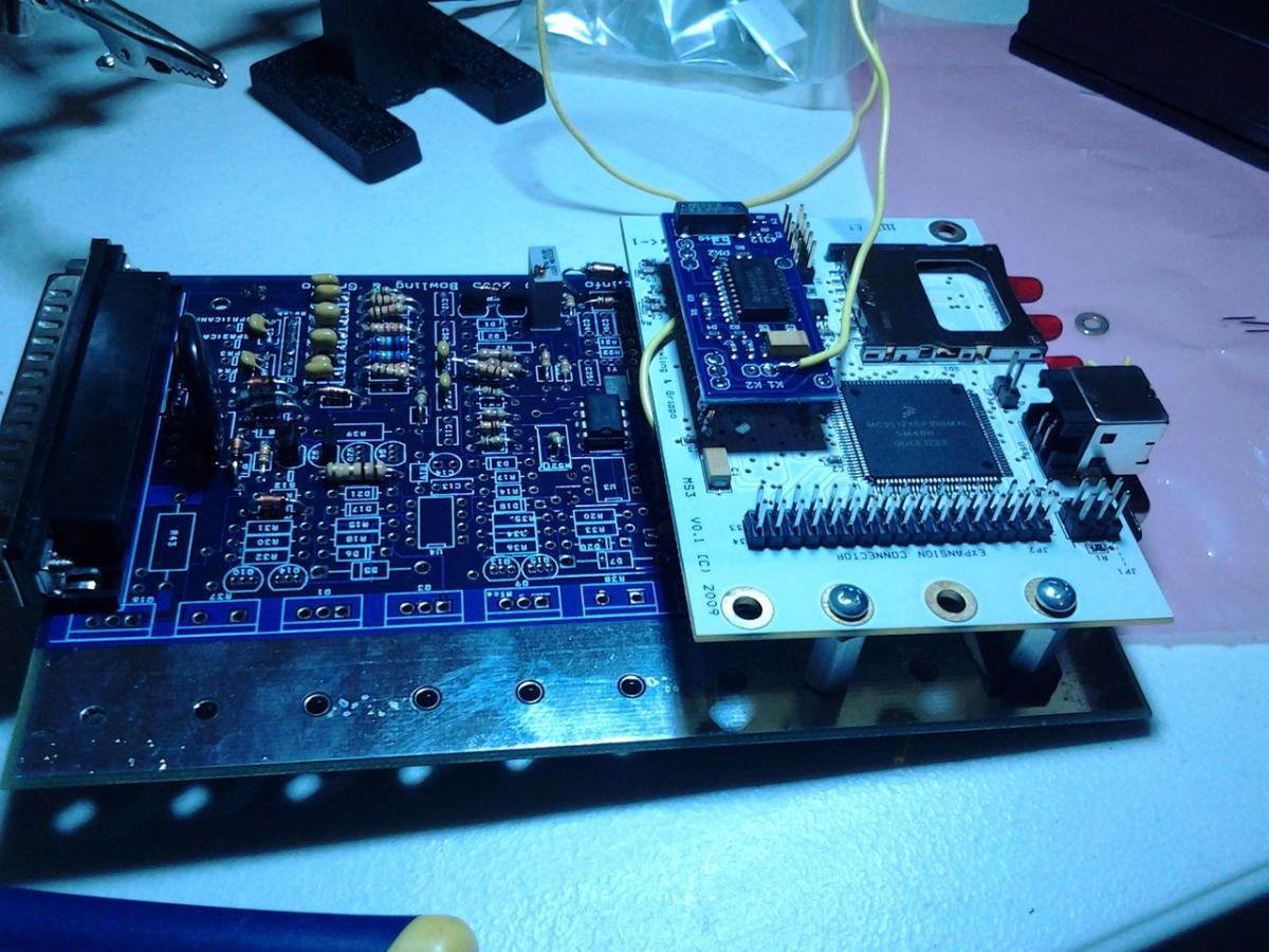
I'm using the Knock Sense and I have it mounted to the MS3 like so:
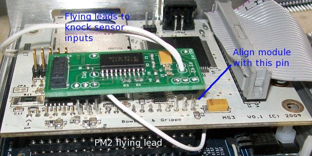
Is there a way I can wire in the K1 so it can be used with the DB37?
ALSO: Do they really only hold the MS3 board in with 2 screws? The third one on the other side seems very important. I evened out the two screws as best I could, but even so it's easy to lift the other side of the board up. Although I haven't mounted it yet in the case.. maybe it's better... but I think not because that is the side where the SD card is.
Last edited by FRT_Fun; 08-21-2013 at 01:47 AM.
Reply
0
0
08-21-2013, 07:50 AM
#8
Boost Czar

iTrader: (62)
Join Date: May 2005
Location: Chantilly, VA
Posts: 79,493
Total Cats: 4,080
You have plenty of options: Spare 1, 2, 3, 4, IAC1A, 1B, 2A, 2B.
i dont understand your last question. once the daughterboard is plugging in and screwed into the heatsink standoffs, it's not going anywhere.
i dont understand your last question. once the daughterboard is plugging in and screwed into the heatsink standoffs, it's not going anywhere.
Reply
0
0
08-21-2013, 10:07 AM
#9
I'm a terrible person
Thread Starter
iTrader: (19)
Join Date: Apr 2009
Location: Arizona
Posts: 7,174
Total Cats: 180
The last question the MS3 board just seemed like there should be a support on the opposite side from the standoffs.
Reply
0
0
08-21-2013, 10:10 AM
#10
Boost Czar
iTrader: (62)
Join Date: May 2005
Location: Chantilly, VA
Posts: 79,493
Total Cats: 4,080
correct.
the board was originally designed for the ms3. the 64 pin socket plus the two screws is enough. Don't worry about it.
One tip I have for you: when you assemble, loosely attach the expander and mainboard to the end plate and slide into the case. Then add the endplate on the sd/usb side and screw the end plates in. Then tighten the studs and dont overtighten them.
Reply
0
0
 08-21-2013, 10:35 AM
#13
I'm a terrible person
Thread Starter
iTrader: (19)
Join Date: Apr 2009
Location: Arizona
Posts: 7,174
Total Cats: 180
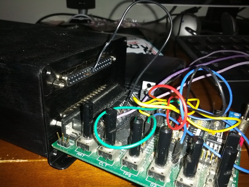
How does that work if I built a JimStimX too. I still haven't done much research past building all these things, but getting there.
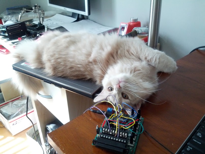
ALSO lol at the cat hair on that stim, that is what a miata turbo owner stim should look like.
ALSO lol at the cat hair on that stim, that is what a miata turbo owner stim should look like.
Reply
0
0
08-21-2013, 10:38 AM
#14
Boost Czar
iTrader: (62)
Join Date: May 2005
Location: Chantilly, VA
Posts: 79,493
Total Cats: 4,080
ALSO lol at the cat hair on that stim, that is what a miata turbo owner stim should look like.
Reply
0
0
 08-21-2013, 10:42 AM
#16
Boost Czar
iTrader: (62)
Join Date: May 2005
Location: Chantilly, VA
Posts: 79,493
Total Cats: 4,080
you need u6 and c26-29 else the USB and/or serial port won't work.
are you going to install flyback didoes for idle control and boost control outputs somewhere on the board, or the harness?
and double check that c16,17,22 are all correct polarity.
are you going to install flyback didoes for idle control and boost control outputs somewhere on the board, or the harness?
and double check that c16,17,22 are all correct polarity.
Reply
0
0
08-21-2013, 10:49 AM
#18
Boost Czar
iTrader: (62)
Join Date: May 2005
Location: Chantilly, VA
Posts: 79,493
Total Cats: 4,080
I noticed Frank had a verison of the components map with those omitted. I had an experience where u6 was damaged/shorted and the USB port didn't work. you're probably okay if it was simply omitted and not shorted/damaged in my case.
in any case, the serial port is disabled without those, just fyi.
in any case, the serial port is disabled without those, just fyi.
Reply
0
0
08-21-2013, 10:51 AM
#19
I'm a terrible person
Thread Starter
iTrader: (19)
Join Date: Apr 2009
Location: Arizona
Posts: 7,174
Total Cats: 180
Ah that makes sense. I'm still trying to understand the circuitry better so I know WHY I'm installing various things, and leaving others out. This is the first PCB I've assembled since high school so it's a bit of an adventure.
Reply
0
0
08-21-2013, 10:55 AM
#20
Boost Czar
iTrader: (62)
Join Date: May 2005
Location: Chantilly, VA
Posts: 79,493
Total Cats: 4,080
haha.
actually, you're missing the vrout to tsel jumper.
and i cant tell but it appears you have the s12c jumper, but i can't see where it's going, possibly to js5 and not js9???
actually, you're missing the vrout to tsel jumper.
and i cant tell but it appears you have the s12c jumper, but i can't see where it's going, possibly to js5 and not js9???
Reply
0
0


