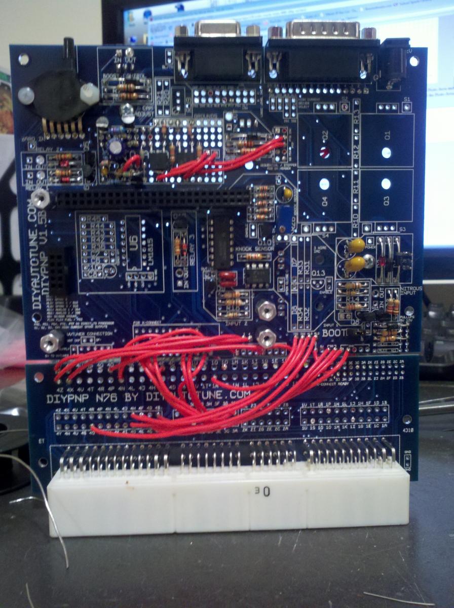
my diypnp mainboard is now assembled
 09-10-2011, 08:31 AM
#1


but i have a few more questions
i have a 1990 1.6 manual all stock
according to step 3 on here http://www.diyautotune.com/diypnp/do..._assembly.html
do i need to jumper anything or not?
and then on this page
http://www.diyautotune.com/diypnp/ap...3-16b6-mt.html
in the notes section where they are talking about the tps
what does SIG mean? i dont see SIG anywhere on the board
is sig short for tps signal? so where it says sig should i just think tps?
i have got a complete 1995 1.8 drive in my garage
while i have the 1.6 in the car now
will the 1.8's vaiable tps fit the 1.6 throttle body?
and i do plan on deleting the afm
i got the gm open element iat sensor
now on the sensor calibration section on the last page i linked
it says "Now you'll do the same for the IAT. Select 'Intake Temperature Sensor' at the top in the drop down box. (NOTE - If you are removing your MAF/AFM as a part of the DIYPNP installation process, do not recalibrate your IAT Sensor now)"
but then later it doesnt say to calibrate it??
when do i do that?
and then in the I/O circuts section
do i just run a jumper from 1Q to 1J? and then remove resistor r14?
and then in misc jumpers it has a couple of things listed then i couple of X's so i guess i do nothing right?
well thats about it for my newb questions
thanks for reading
any input is really appreciated
jared

Reply
 0
0

0
09-10-2011, 08:31 AM
#2
oh and i had a bag of resistors that included r10-r13 included
but i cant find any of those on the main board
do they exist?
and for inj1 and inj2 they say to hook up to 4U and 4V
and there are four connections on the main board for each inj
im guessing it doesnt matter which of the four holes i choose?
thanks again
but i cant find any of those on the main board
do they exist?
and for inj1 and inj2 they say to hook up to 4U and 4V
and there are four connections on the main board for each inj
im guessing it doesnt matter which of the four holes i choose?
thanks again
Reply
0
0

 09-10-2011, 03:09 PM
#11
if only i knew where at on the harness connector board that was.
and then after i figure that out then what?
i just take the tps signal straight from the harness connector board via resistor to ground on the main board?
i dont see how that gives the ecu the signal but then im obviously no genius
and then after i figure that out then what?
i just take the tps signal straight from the harness connector board via resistor to ground on the main board?
i dont see how that gives the ecu the signal but then im obviously no genius
Reply
0
0
09-10-2011, 04:13 PM
#12
Boost Czar


iTrader: (62)
Join Date: May 2005
Location: Chantilly, VA
Posts: 79,493
Total Cats: 4,080
Originally Posted by http://www.diyautotune.com/diypnp/apps/n76/usdm-mazda-miata-9093-16b6-mt.html
* Jump SIG to 4L for variable TPS retrofit ONLY!
*** Jump VREF to 1N for variable TPS ONLY!
*** Jump VREF to 1N for variable TPS ONLY!
match those wires on your oem tps connector to the appropriate ones on your vTPS.
Reply
0
0
09-10-2011, 04:32 PM
#16
ok so i eithor ground 4d or 4l via resistor
doesnt really matter which? they are both for the tps?
and now in this manner the ecu is not getting a tps signal?
so do i calibrate it or not?
or are those calibration directions on diypnp.com the directions fr the oem tps?
thanks
i really do appreciate your input
doesnt really matter which? they are both for the tps?
and now in this manner the ecu is not getting a tps signal?
so do i calibrate it or not?
or are those calibration directions on diypnp.com the directions fr the oem tps?
thanks
i really do appreciate your input
Reply
0
0
09-10-2011, 08:42 PM
#19
i have been searching and searching and i aint got a clue as to how to get this thing going.
i have downloaded and installed megatune and tuner studio
but i dont have a clue what to do
all i know is that i think i have to flash it with firmware first
then load my base maps
i dont have a clue as to how to do either
i have downloaded and installed megatune and tuner studio
but i dont have a clue what to do
all i know is that i think i have to flash it with firmware first
then load my base maps
i dont have a clue as to how to do either
Reply
0
0


