12V triggered COPS
 01-29-2010, 08:39 AM
#1
Elite Member
Thread Starter
iTrader: (1)

Join Date: Jun 2006
Location: Warrington/Birmingham
Posts: 2,642
Total Cats: 42
I bought some COPS for my new motor as I didn't get 2001 (nearly) COP's included with it, and my MK1 coilpacks don't have anywhere to live.
Unfortunately I got the wrong ones.... only realising this after making brackets and wiring looms etc. They're also brand new unused and were cheap
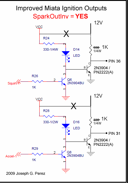
I think they're triggered by a 12v source, (they''l spark on the bench with 12v aplied to the trigger). I thought the 5's stock coils were ground triggered but from reading Joe's improve spark output mods (which I have done), it's actually 5v triggered, correct?
Question is, can I pull R28 and R24 from their 5v feed (VCC), and supply them with 12v from elsewhere on the board to trigger my COPS, or am I going to blow **** up?

(Please don't suggest getting the right COPs, I've been trying to do that for years)
Unfortunately I got the wrong ones.... only realising this after making brackets and wiring looms etc. They're also brand new unused and were cheap
I think they're triggered by a 12v source, (they''l spark on the bench with 12v aplied to the trigger). I thought the 5's stock coils were ground triggered but from reading Joe's improve spark output mods (which I have done), it's actually 5v triggered, correct?
Question is, can I pull R28 and R24 from their 5v feed (VCC), and supply them with 12v from elsewhere on the board to trigger my COPS, or am I going to blow **** up?
(Please don't suggest getting the right COPs, I've been trying to do that for years)

Reply
 0
0

0
01-29-2010, 08:46 AM
#2
Elite Member

iTrader: (10)
Join Date: Jun 2006
Location: Athens, Greece
Posts: 5,976
Total Cats: 355
The stock 2001+ units will trigger on either 12V or 5V. You need to raise the voltage to 5/12 to begin saturating the coil, and then pull low to discharge. FIY attached are the stock trigger signals (12V) and the "modified" 5V signal from a J&S timing retard unit. Sorry for the blurry pics, I only had a cellphone with me.
Jim
Jim
Reply
0
0
01-29-2010, 08:58 AM
#3
Elite Member
Thread Starter
iTrader: (1)
Join Date: Jun 2006
Location: Warrington/Birmingham
Posts: 2,642
Total Cats: 42
Cheers Reverant.
I don't have the stock 2001 units though, they weren't included with my motor :(
I got some Toyota COPS from eBay, part number is 90919-02238 they're for a 2ZZ motor (see the mistake I made there
I don't have the stock 2001 units though, they weren't included with my motor :(
I got some Toyota COPS from eBay, part number is 90919-02238 they're for a 2ZZ motor (see the mistake I made there
Reply
0
0
01-29-2010, 03:17 PM
#4
Elite Member
Thread Starter
iTrader: (1)
Join Date: Jun 2006
Location: Warrington/Birmingham
Posts: 2,642
Total Cats: 42
After much research I think my COPs do indeed have ignitors in them, but they're triggered from 12v rather than the 5v that the stock MK1/MK2 coils trigger off.
Apparently all I need to do is this, which is definately FTW, it'll take about tem minutes to do this mod, happy ****** days
Just posting for future searches
Apparently all I need to do is this, which is definately FTW, it'll take about tem minutes to do this mod, happy ****** days
Just posting for future searches
Reply
0
0
01-29-2010, 04:46 PM
#6
Elite Member
Thread Starter
iTrader: (1)
Join Date: Jun 2006
Location: Warrington/Birmingham
Posts: 2,642
Total Cats: 42
Cheers Joe, and thanks for the picture
One thing, can anyone explain to me why you need to increase the impedance of the resistors when using 12v over 5v for a pullup?
One thing, can anyone explain to me why you need to increase the impedance of the resistors when using 12v over 5v for a pullup?
Reply
0
0
01-29-2010, 05:31 PM
#9
Boost Pope

iTrader: (8)
Join Date: Sep 2005
Location: Chicago. (The less-murder part.)
Posts: 33,015
Total Cats: 6,587
Those resistors are there for current-limiting. Their job is to make sure that only enough current passes through the circuit to satisfy the needs of the load device (the COP trigger input), and no more. If there were no resistors at all, then when the two 3904 transistors were turned on (and conducting from collector to emitter), an infinite amount of current would pass through them, and they would explode.
As shown in the above equation, for any given voltage (E), the higher the resistance (R), the lower the current flow (I). If you increase the voltage and do not change the resistance, then the current will also increase.
The goal here is to protect the transistors. Even if you are not passing enough current to cause them to physically explode, the more current you shove through them, the more heat is generated within them. This degrades their electrical performance and shortens their life expectancy.
Looking at the 2N3904, it is rated to pass 200 milliamps, and dissipate a maximum of 625 mW. (Power dissipation get a little trickier; it's P = E x I, where E in this case is the known collector saturation voltage of the transistor [about 0.3v], and I is the solution from the first formula.)
Ok, so with 5 volts and 330 ohms, the current flow through the transistor (when on) is 15ma. Barely a tickle. If we increase to 12 volts, current goes up to 36ma.
Truthfully, this still isn't much now that I think about it. Chances are excellent that the transistor will still enjoy a long, full life. If anything, the turn-on performance of the coil primaries will improve slightly.
I honestly don't know where this suggestion to increase the resistors to 1k came from. If it was something I said, then I'm not sure why I said it. What you get by doing that is to reduce current back to 12ma, which is as near as makes no difference to what you were getting at 5v and 330 ohm. And frankly, even the 330 ohm choice was pretty arbitrary on my part. I've built these circuits with 100 ohm resistors (50ma) and they work just fine and dandy.
Use the 330s.
edit: Rev beat me to it. Still, go ahead and use the smaller value parts. They'll be fine.
Reply
0
0
01-29-2010, 06:10 PM
#10
Elite Member
Thread Starter
iTrader: (1)
Join Date: Jun 2006
Location: Warrington/Birmingham
Posts: 2,642
Total Cats: 42
Joe, that explanation is brilliant many many thanks.
The 1k resistors came from Jean (of JBPerf fame), but if sticking with the 330Ohm resisters is fine, I'll do that, purely through laziness
The 1k resistors came from Jean (of JBPerf fame), but if sticking with the 330Ohm resisters is fine, I'll do that, purely through laziness
Reply
0
0
02-05-2010, 09:29 AM
#12
Elite Member
Thread Starter
iTrader: (1)
Join Date: Jun 2006
Location: Warrington/Birmingham
Posts: 2,642
Total Cats: 42
In an attempt to tidy up my board (getting the COPS working on a monday evening was a bad idea and a bit of part scavenging took place). I want to replace all the transistors in this circuit.
However my local store only has 1 2N3904 in stock, I want/need at least 4...
Can I use a 2N5551, the ratings are waaaaay over the 2N3904 from their tech specs on this website
Low Power LF NPN Transistors TO92 Case : Transistors : Maplin
Seeing as Joe's already worked out i'll be pulling max 36ma I could use pretty much anything in that list, correct?
I'm confused by what the max/min fields are for though, would a high voltage cause me any issues (2nd column), and the frequency of the transistor.
Sorry for the dumb-*** questions.
Reply
0
0
02-05-2010, 11:57 AM
#13
Boost Pope
iTrader: (8)
Join Date: Sep 2005
Location: Chicago. (The less-murder part.)
Posts: 33,015
Total Cats: 6,587
Ah, well, that explains it. Jean is Canadian. The Canadians are the bastard children of the French. French people are communists, and communists can't design good electronics. 
(Jean, if you're reading this, I'm just kidding. Your P&H board is awesome, and if it weren't for the JimStim, I'd really hate my life.)
Yup. The important facts for our application are the IC, VBE(sat), hFE, and PD, and those all look good. I would advise using the same type of part (ie: all 2N5551s) for each circuit- you don't want the two halves of your ignition trigger to have different turn-on characteristics.
hFE is DC current gain, which is the relationship between current drawn on the base and current passed through the collector. An hFE of 200 would mean that for 1ma driving the base, you can pass 200ma through the collector. As with many things in life, there's a tolerance here, so min/max say that the transistor is guaranteed to fall somewhere within that range (and will vary with case temperature and other factors as well.)
VCEO is a maximum rating. It means that you may apply no more than the specified voltage to the part. From a practical standpoint, as VCEO increases, the saturation voltages also tend to increase, and in some circuits this can be a bad thing. In this particular application you're well over minimums so it's not important.
fT (current gain bandwidth product), which is the "frequency" you're referring to, is irrelevant in a low-speed switching application like we're doing.
(Jean, if you're reading this, I'm just kidding. Your P&H board is awesome, and if it weren't for the JimStim, I'd really hate my life.)
I'm confused by what the max/min fields are for though, would a high voltage cause me any issues (2nd column), and the frequency of the transistor.
VCEO is a maximum rating. It means that you may apply no more than the specified voltage to the part. From a practical standpoint, as VCEO increases, the saturation voltages also tend to increase, and in some circuits this can be a bad thing. In this particular application you're well over minimums so it's not important.
fT (current gain bandwidth product), which is the "frequency" you're referring to, is irrelevant in a low-speed switching application like we're doing.
Reply
0
0
02-06-2010, 11:03 PM
#16
Newb

Join Date: Feb 2010
Posts: 35
Total Cats: 0
Hey Joe you bastard (just kidding ) I think you forgot about the power rating of the resistors. With 12V they'll dissipate about 0.5W (depending on the duty cycle of course). That's why I went with 1K (to keep it at 1/4W).
And _I_ am the man (again just kidding because you know a lot more about Miatas than I do).
Jean
) I think you forgot about the power rating of the resistors. With 12V they'll dissipate about 0.5W (depending on the duty cycle of course). That's why I went with 1K (to keep it at 1/4W).And _I_ am the man
(again just kidding because you know a lot more about Miatas than I do).Jean
Reply
0
0
02-07-2010, 11:02 PM
#17
Boost Pope
iTrader: (8)
Join Date: Sep 2005
Location: Chicago. (The less-murder part.)
Posts: 33,015
Total Cats: 6,587
Well how do you like that? I rip on Jean (who has never been on here so far as I know) and the very next day he shows up.
Something fishy afoot.
Oooh, self-pwn. Yeah, I forgot that not everyone knows about power ratings.
Obviously I've never scoped whatever coils rich is using, but I have looked at the voltage/current profile on the igniter and primary side of the stock ignition system. I found that with 1k at 5v, the rising edge was really slow, to the point that saturation took quite a while longer to achieve. At 330 ohms (15ma) it cleaned up quite a bit, and at 100 ohms (50ma) it was killer.
... which is why I suggest low pullup values. And yeah, at 12v you'll need a larger body part. Radioshack has half-watt 330s for 99 cents: 330 ohm 1/2W 5% Carbon Film Resistor
Ok, we can both be the man.
Something fishy afoot.
I think you forgot about the power rating of the resistors.
Obviously I've never scoped whatever coils rich is using, but I have looked at the voltage/current profile on the igniter and primary side of the stock ignition system. I found that with 1k at 5v, the rising edge was really slow, to the point that saturation took quite a while longer to achieve. At 330 ohms (15ma) it cleaned up quite a bit, and at 100 ohms (50ma) it was killer.
... which is why I suggest low pullup values. And yeah, at 12v you'll need a larger body part. Radioshack has half-watt 330s for 99 cents: 330 ohm 1/2W 5% Carbon Film Resistor
And _I_ am the man (again just kidding because you know a lot more about Miatas than I do).
(again just kidding because you know a lot more about Miatas than I do).
Reply
0
0
02-07-2010, 11:10 PM
#18
Newb
Join Date: Feb 2010
Posts: 35
Total Cats: 0
Obviously I've never scoped whatever coils rich is using, but I have looked at the voltage/current profile on the igniter and primary side of the stock ignition system. I found that with 1k at 5v, the rising edge was really slow, to the point that saturation took quite a while longer to achieve. At 330 ohms (15ma) it cleaned up quite a bit, and at 100 ohms (50ma) it was killer.
Jean
Reply
0
0
02-08-2010, 03:50 AM
#19
Elite Member
Thread Starter
iTrader: (1)
Join Date: Jun 2006
Location: Warrington/Birmingham
Posts: 2,642
Total Cats: 42
Crap... Guess I'm pulling my MS apart again this weekend! lol
I actually already had 1k resistors in there, they're the originals from when i first built the board back in 2005/6.
Will it really make that much of a performance difference to my ignition though?
I actually already had 1k resistors in there, they're the originals from when i first built the board back in 2005/6.
Will it really make that much of a performance difference to my ignition though?
Reply
0
0
02-08-2010, 12:38 PM
#20
Boost Pope
iTrader: (8)
Join Date: Sep 2005
Location: Chicago. (The less-murder part.)
Posts: 33,015
Total Cats: 6,587
What happens when you use a high value resistor is that it takes longer for the coil primary to charge. The igniter circuit seems to load its trigger input pretty heavily at turn-on, such that the voltage on the trigger line gets pulled down. This seems to correspond to a a decrease in the rate at which current through the primary winding builds.
Here is an example of what I'm talking about:

The yellow trace is voltage on the trigger line, and the blue trace is current through the coil primary. See how when the trigger first turns on, the voltage starts out very low and then builds up, almost as though the igniter itself is reaching a saturation point? As you use smaller value resistors (and thus increase the available drive current) the rise of this waveform is much less retarded.
Where this becomes important is that I observed a correlation between the rise time of the trigger voltage and the rise time of the primary current. It's not a linear relationship, but it does happen. As you make more current available to the trigger (and thus increase its voltage) the current in the primary builds more rapidly. In this picture, you can see that the primary current never did reach full saturation (which would be indicated by the blue trace leveling out and becoming horizontal). When trigger drive was increased, the primary was able to become saturated within the time allowed.
(Keen-eyed viewers will note that the dwell time on this capture is less than what's specified for an NA. I believe that this particular trace was actually taken back when I had my EMU, I just can't find any of the more modern stuff right now.)
Ok, now the practical upshot of all this is that what I have illustrated here (limiting trigger current too much) is roughly equivalent to decreasing your dwell time. Both have the effect of limiting the amount of charge which the coil can build prior to firing. If you have the ability to measure DC current with a scope, you can tune the dwell time of an MS built with the 1k pullups until you reach coil saturation.
Or, you can just install smaller resistors.
Reply
0
0


