Oochi's MS3X DIY Build
 01-21-2012, 01:57 AM
#1
Junior Member
Thread Starter

Join Date: May 2011
Location: Central Kentucky
Posts: 221
Total Cats: 1
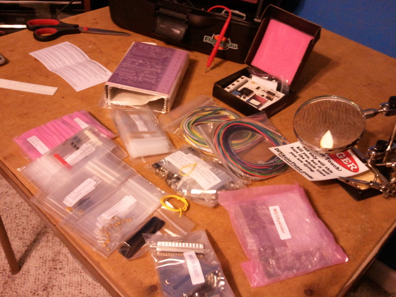
Hello, I got all (most) of my MS3X parts in and I have started the build! This is for a 90 with stock 1.6 btw. I figured I would make a build thread because I know I will have questions and don't want to screw this up, plus you guys know more than me. anyway, So far it has gone quite smooth. A couple things that I am confused about. I got the resistors in, then diodes, now working on capacitors. One thing I am confused on is I have a resistor in a baggy by itself labeled "BIP373 330o, 330QBK-ND" i know it is a 330ohm resistor, but i cannot find it anywhere in the manuals. I have been using www.msextra.com as a reference. Another thing is...
I'm not sure what this means! Please review my progress and let me know what I do wrong, or any other recommendations. I will update this as often as I work on it. Will be during weekends due to college.
PICS:
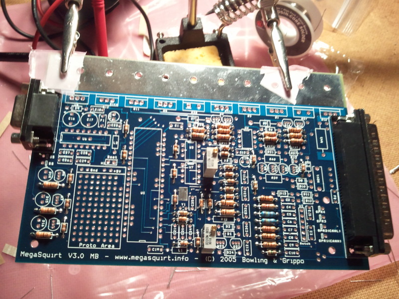
12) Next get all the bags of capacitors together, keeping them in the bags (C1, etc).
If you’re using the coil –ve as the trigger input go to step 15 (This is rare now.) Note that you CANNOT trigger from coil negative if you are trying to run ignition or sequential fuel - you need a trigger-wheel arrangement.
13) As long as you’re NOT using the coil –ve as the trigger input (Fuel only) find C30 and instead install it in H1/Boot (This adds smoothing to the battery voltage measurement and reduces the chance of noise getting injected into the CPU from the 12V line.)
PICS:
Last edited by Oochi; 01-23-2012 at 11:05 PM.

Reply
 0
0

0
01-21-2012, 06:19 AM
#2
Senior Member

Join Date: Nov 2007
Location: Belgium
Posts: 999
Total Cats: 73
You're not following the correct instructions. You've already installed a bunch of components you don't need.
Take a look at my build how-to's. They work just as well on a NA (don't build the alternator circuit, it's not needed on a NA).
Take a look at my build how-to's. They work just as well on a NA (don't build the alternator circuit, it's not needed on a NA).
Reply
0
0
01-21-2012, 01:13 PM
#3
Junior Member
Thread Starter
Join Date: May 2011
Location: Central Kentucky
Posts: 221
Total Cats: 1
well thats just great! would it hurt to leave whatever isnt needed in there? and are you saying to follow http://westfieldmx5.devocht.com/mega...egasquirt-ms3/ and http://www.megamanual.com/ms2/V3assemble.htm ? I was just following the directions that diyautotune sent me to look at.
Reply
0
0
 01-23-2012, 10:21 PM
#7
Boost Pope


iTrader: (8)
Join Date: Sep 2005
Location: Chicago. (The less-murder part.)
Posts: 33,015
Total Cats: 6,587
Long story short: You can build the unit "fully" according to the primary documentation and nothing is lost. Since you are using the MS3X, your build will be particularly simple as you needn't bother with any of the old-style "hacks".
As to the quote in your first post, you are not going to be triggering from coil -ve. That applies only to cars with distributors and breaker-point ignition. (Remember, the MS project has its roots in the old-school American Iron community. They see nothing wrong with distributors, throttle-body injection, separate water fountains for brown people, and arranged marriage.)
Reply
0
0
01-24-2012, 02:42 AM
#8
Elite Member
iTrader: (10)
Join Date: Jun 2006
Location: Athens, Greece
Posts: 5,976
Total Cats: 355
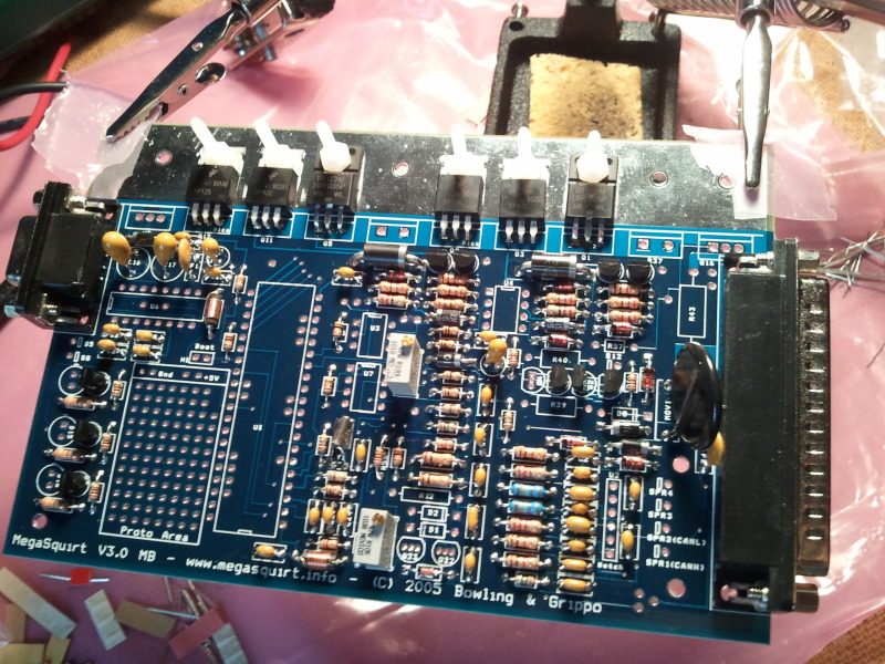
I don't see a heatsink under the FETs. You can get away if you are only using U5, but not with that many. Oh, and you must not use nylon screws and nuts on the FETs that get hot.
Reply
0
0
01-24-2012, 03:15 PM
#9
Junior Member
Thread Starter
Join Date: May 2011
Location: Central Kentucky
Posts: 221
Total Cats: 1
 Wow. I can't believe i forgot to put the heatsink on. Double and thanks for the info on the nylon screws, i was thinking about that when i put them on but I thought i saw other pictures with them on there so I assumed it would be fine but i will change them this weekend. Appreciate the help!
Reply
0
0
01-25-2012, 08:25 AM
#10
Senior Member
Join Date: Nov 2007
Location: Belgium
Posts: 999
Total Cats: 73
I'm not sure why R19 is not there. It's required with the TIP120 mod.
I'm sure Brain can explain the raison behind it.
Last edited by WestfieldMX5; 01-25-2012 at 08:55 AM.
Reply
0
0
01-25-2012, 08:39 AM
#11
Boost Czar

iTrader: (62)
Join Date: May 2005
Location: Chantilly, VA
Posts: 79,484
Total Cats: 4,076
I'm not sure I made that one. But if the MS3x is doing the idle, you dont need r19. And really R1 isn't needed IIRC.
This is the only I've made, but it still has more than you need:
This is the only I've made, but it still has more than you need:

Reply
1
1
01-25-2012, 04:37 PM
#14
Elite Member
iTrader: (37)

Join Date: Apr 2010
Location: Very NorCal
Posts: 10,441
Total Cats: 1,899
Good luck Oochi, I'll be watchin'
Reply
0
0
01-25-2012, 04:54 PM
#16
Junior Member
Thread Starter
Join Date: May 2011
Location: Central Kentucky
Posts: 221
Total Cats: 1
And that is what really gets me about the MS and why I paid Scott to build one. I want to do a carb -> EFI project in the future but figuring out the MS2 documentation is a bloody nightmare. I'm just glad you guys who DO understand it are willing to give advice/suggestions/abuse to help keep us noobs pointed in the right direction.
Good luck Oochi, I'll be watchin'
Good luck Oochi, I'll be watchin'
Reply
0
0
01-27-2012, 06:26 PM
#17
Junior Member

Join Date: Mar 2011
Location: Guildford, UK
Posts: 163
Total Cats: 0
All the build confusion boils down to how good the MS really is. You can build it configured specific to your actual car or the general model or for a lawn mower. Fantastically versatile.
Reply
0
0
01-29-2012, 03:55 PM
#20
Senior Member
Join Date: Nov 2007
Location: Belgium
Posts: 999
Total Cats: 73
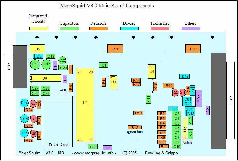
Study this http://www.megamanual.com/ms2/pcb.htm
Look up the parts that you're not sure about and see what they do.
U3 is the opto-isolator, so if you need it or not depends on how you wire the tach inputs.
Brain's diagram assumes you use the opto circuit (U3) as crank input and JS10 as cam input as discussed in this thread.
My diagram assumes you use the VR circuit (U7) as crank input and the VR circuit on the MS3X asd cam input.
Same result, done differently.
The only transistor you need on the heatsink is U5. The rest of the parts on the heatsink are for the injector circuit, but you can leave those parts out because you use the injector outputs on the MS3X instead of those on the main board. IOW, everything you installed on the heatsink up to now, including R37 and R38, is not needed.
Same thing with the idle circuit, you use the one on the MS3X instead of building the one on the mainboard.
You really need very little parts from the mainboard.
Last edited by WestfieldMX5; 01-29-2012 at 04:47 PM.
Reply
0
0


