When you click on links to various merchants on this site and make a purchase, this can result in this site earning a commission. Affiliate programs and affiliations include, but are not limited to, the eBay Partner Network.
Seeking advice on wiring wideband a/f gauge to MS3x.
I'm getting to the point in my build where it's time to wire up the MegaSquirt 3x. This is my first experience with it and I'm seeking some wiring advice. I've already searched hi and low on this forum and the interwebs and I haven't seen a definitive answer. So I thought I'd ask the group.
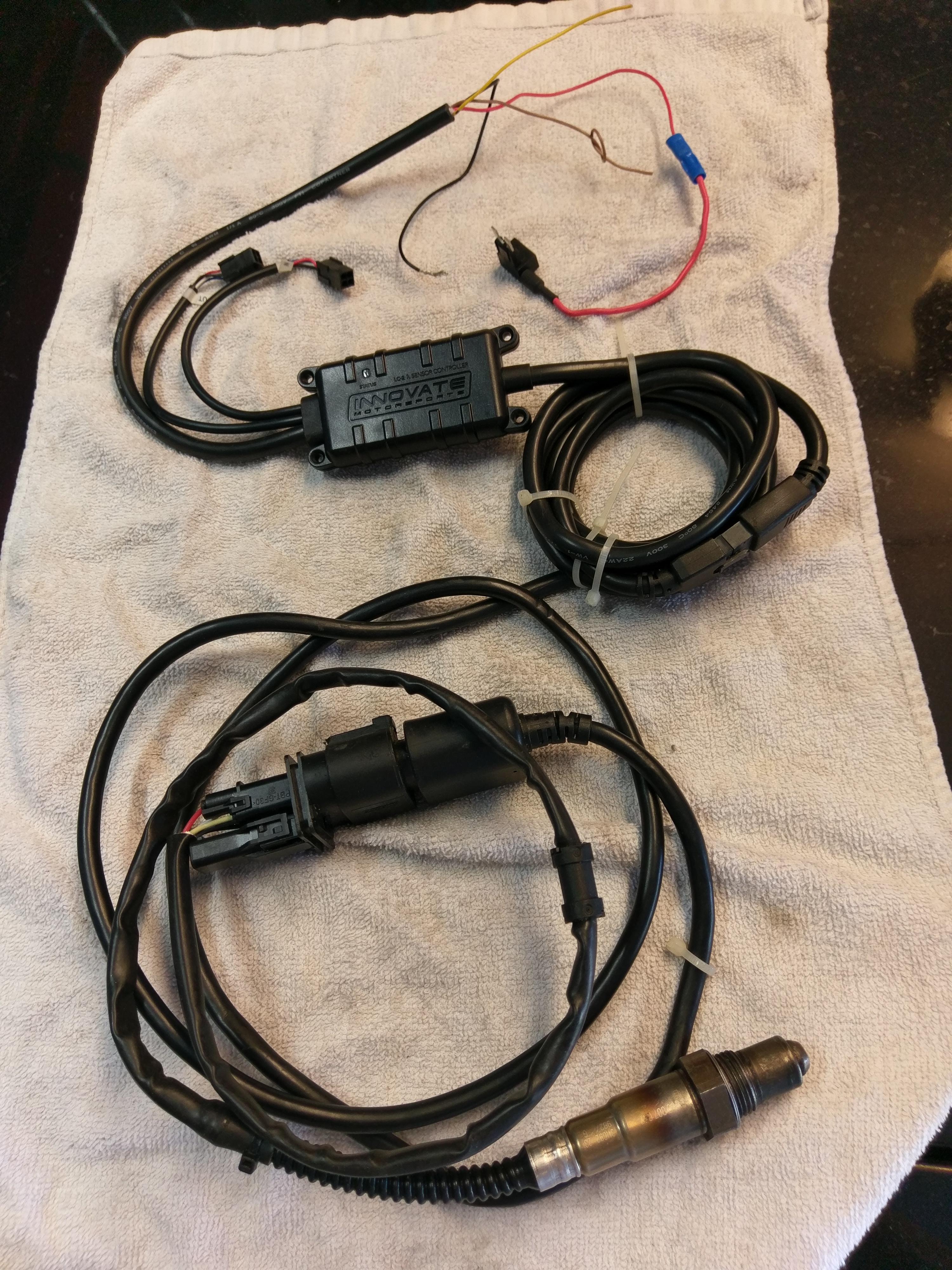
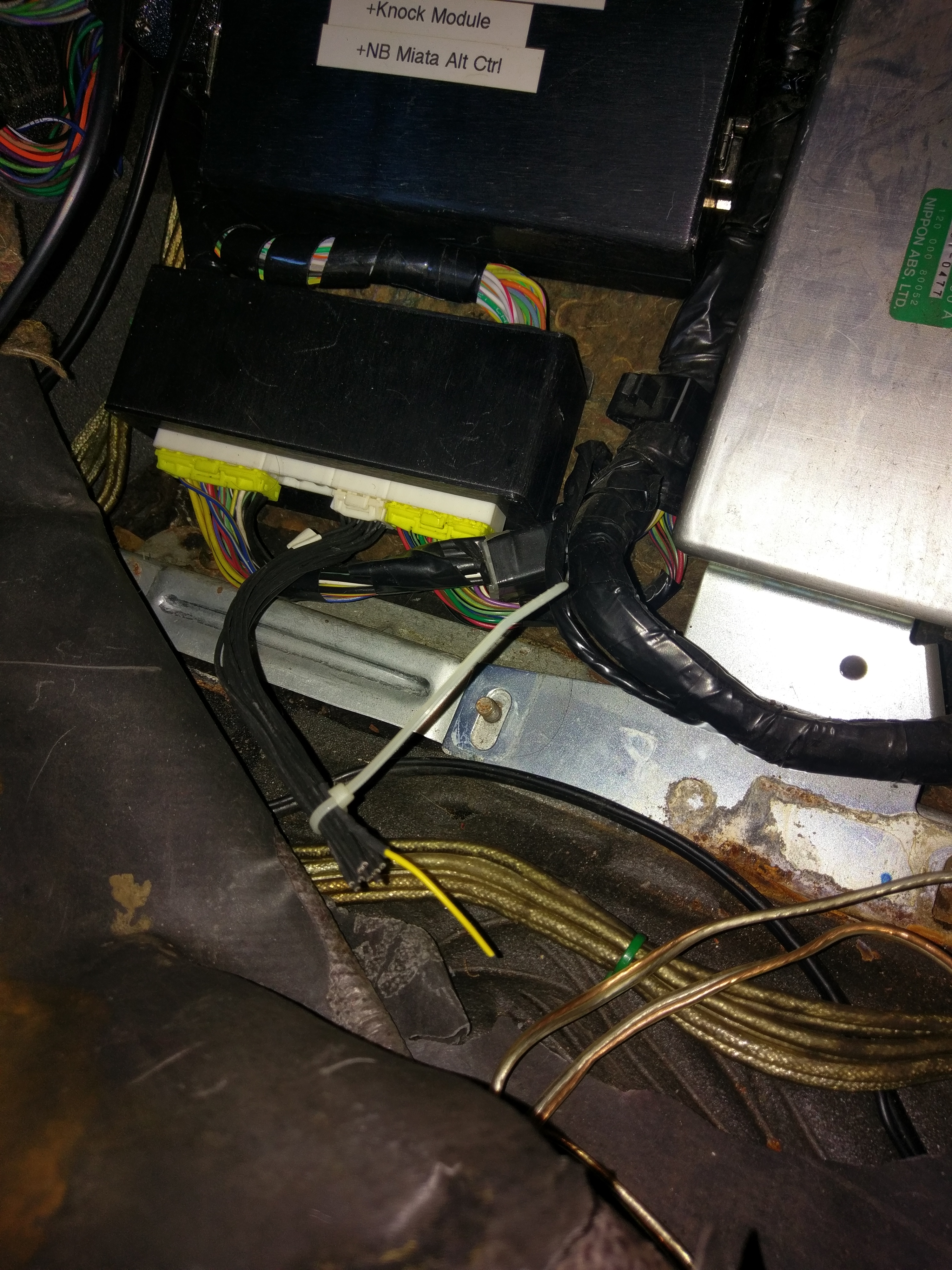
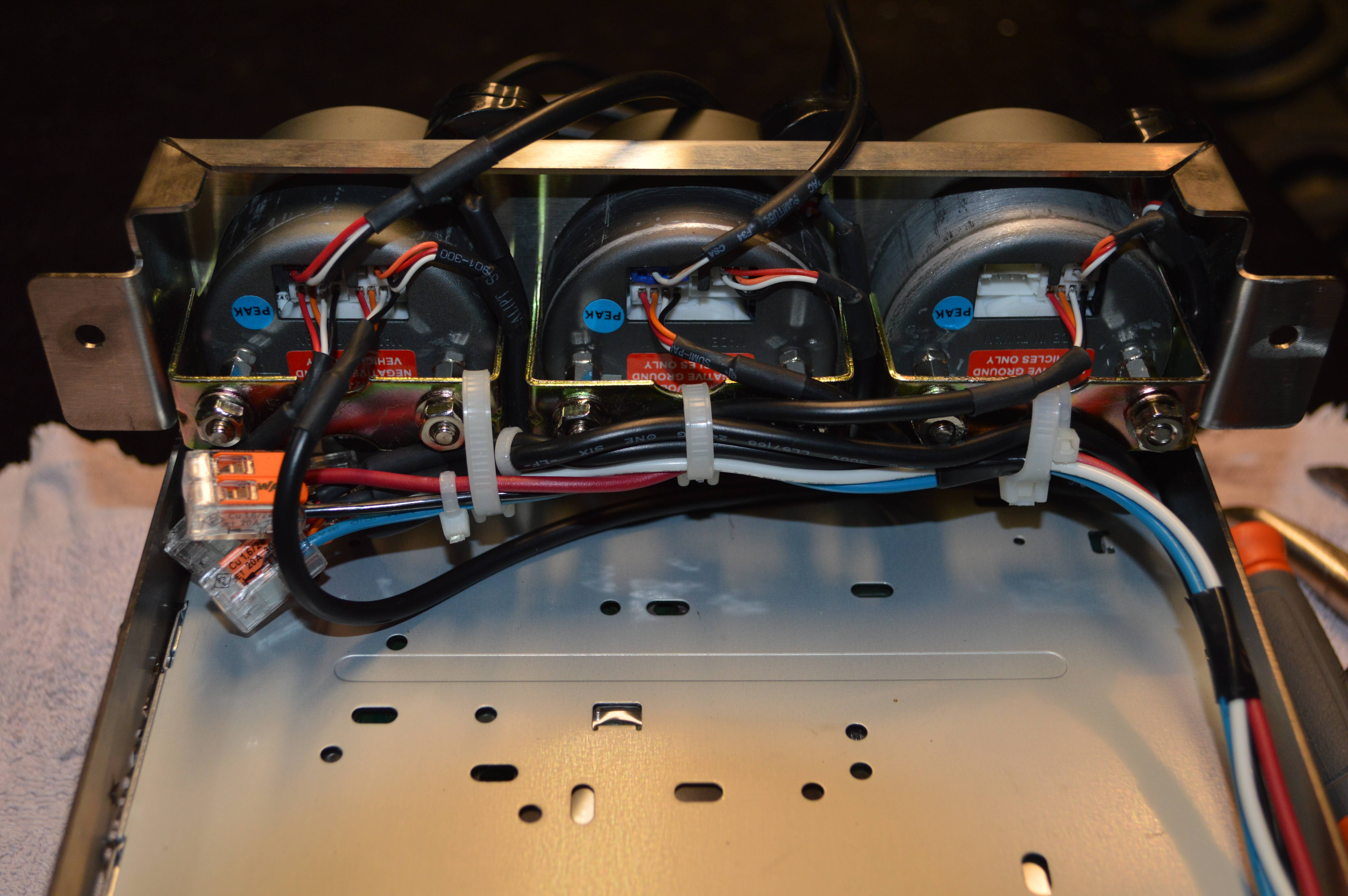
This MS3x was originally installed on a 2000 NB. The PO used an Innovate Lambda controller with the wideband O2 sensor and the O2 sensor harness was spliced to the ECU connector bus via the yellow wire (indicated at the top of the picture 1 [LCS]). The yellow wire from the LCS was the only wire spliced into the yellow wire of the small harness (shown in picture 2).
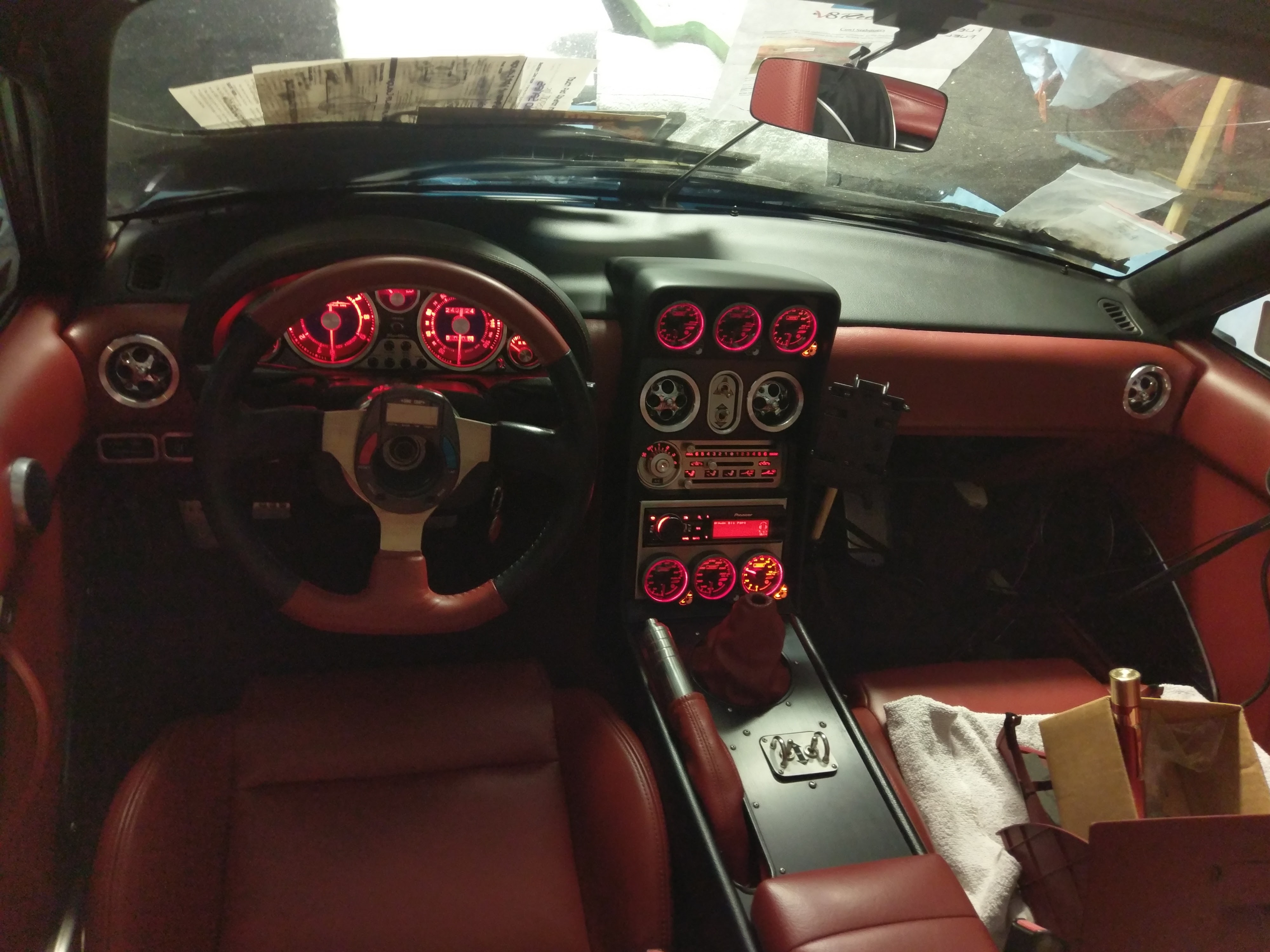
For my build (1993 GReddy turbo built engine - Eagle rods/Wiseco pistons/race bearings, etc.), I am using six ProSport Halo gauges, including an analog (sweeping) wideband A/F gauge with a proprietary controller.
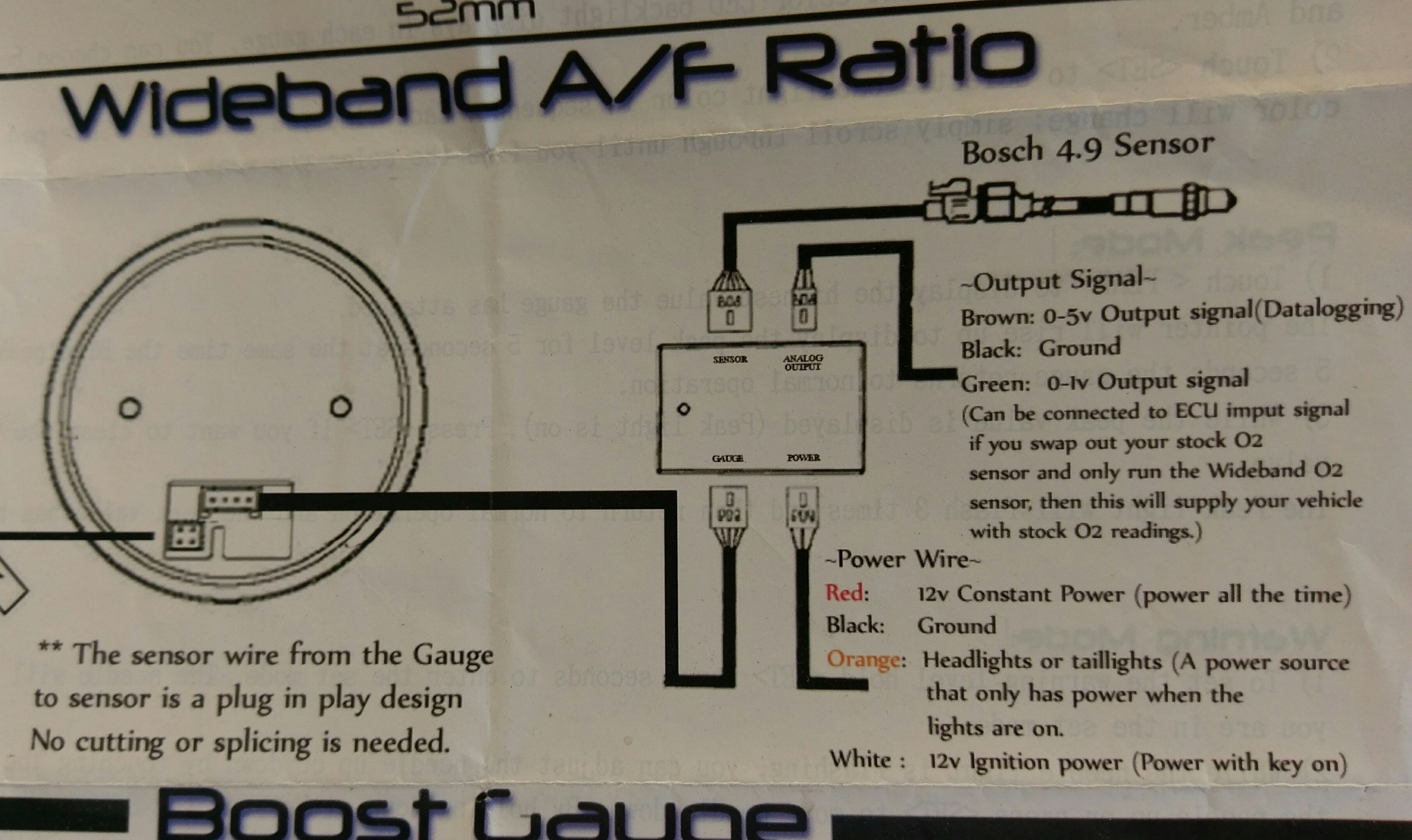
My question is this - which wire do I splice from the -Output Signal- harness to the connector on the MegaSquirt? I'm assuming it's the green wire, as indicated in the instructions (picture 3).
Additionally, is there anywhere I can splice the brown wire for datalogging via the MS?
Thank you all for your prompt and thoughtful replies. They answered exactly the question I was asking.
Originally Posted by ridethecliche
This might help
I thought I saw all of B&B's videos, but I obviously missed this one.
Originally Posted by mmmjesse
Brown wire to the MS. Green wire is a narrow band signal to make a stock ecu happy and will be irrelevant on your car.
Thanks for explaining. I didn't realize one wire is narrowband and the other is wideband. The video above indicated that, too.
Originally Posted by Braineack
I'd wire it completely to that i/o plug on your DIYBOB. the only exception being that you need to source the headlight wire from under the dash (like the radio harness).
All the gauges, including the A/F Ratiometer are already wired up with the exception of the output signal harness from the wideband.
The only gauge issue remaining is that now that I've installed the SETRAB oil cooler and sandwich plate, I don't have a port for my oil temp sensor.
FYI - the gauges I'm running are (top 3) A/F ratiometer, boost, EGT, (bottom 3) oil temp, fuel pressure and voltage.
Drill and tap sandwich plate for the sensor or risk a tee fitting inline on the hose to intercept the temp. Or switch to a sandwich that is tapped for sensors already like so many on ebay.
the like whole point of the DIYBOB is so you can easily hook this ****** up... this is a 2min job at most.jump 1A, 1B, 4A, and 4D to the 2A-2L connector.connect Red with 1A, White with 1B, Power Ground with 4A, Signal Ground to 4D, and Brown to the cut yellow wire already wired up for wb02 in.
OKAY, OKAY...I'll do it. Thanks for the write-up. I wouldn't have known how to do it otherwise.
the like whole point of the DIYBOB is so you can easily hook this ****** up... this is a 2min job at most.
jump 1A, 1B, 4A, and 4D to the 2A-2L connector.
connect Red with 1A, White with 1B, Power Ground with 4A, Signal Ground to 4D, and Brown to the cut yellow wire already wired up for wb02 in.
Apologies for necro, but I'm just seeking clarification.
Is this what you mean by jumping the 1A, 1B, 4A and 4 D to the 2A-2L connector? I'm using trubokitty and I'm wondering if I'm not even going to use the Pink MS-23 wire into 2N if I'm installing wideband.
2 on the BOB is not connector 2 on the 93 chassis. Its actually connector 4 on the BOB that you need to connect to. 1=1 and 2=4 for chassis to bob connectors. move all those you did on 2 to 4. I imagine its probably not running right now.
I need to eliminate a lot of the wires from the premade DIYAutotune harnesses, but I was using your guide to put the connector together, so that's the reasoning for tachout and the crowded spare 16 pin.
So to see if I'm interpretying this correctly, jump (solder a wire into) 4A->2F, 4D->2H, 1A->2D, 1B->2B (is it okay to have 2 wires going to the same pin? I guess I technically do with the grounds), you made a mark from 3C->2J, as well as over 1B.
I'm not trying to sound dumb I'm just trying to get an exact picture here, so yours is much appreciated.
MmmJesse just pointed out that I should switch everything I have on 2 to 4, as I seem to have read something incorrectly.
2 on the BOB is not connector 2 on the 93 chassis. Its actually connector 4 on the BOB that you need to connect to. 1=1 and 2=4 for chassis to bob connectors. move all those you did on 2 to 4. I imagine its probably not running right now.
Is that what I'm missing here? Switch everything I have on 2 to 4? The MS is not running right now, you are correct. I haven't finished it yet.
Also, if you are still running the factory engine harness, you dont need to do tacho out. for the 1.6, the tacho is driven at the ignitor. Only time you would need tacho out is if you went with different ignition control like i have on my 93 now. I previously ran my 93 with the stock engine using the exact info above for a while with no issues.
Also, if you are still running the factory engine harness, you dont need to do tacho out. for the 1.6, the tacho is driven at the ignitor. Only time you would need tacho out is if you went with different ignition control like i have on my 93 now. I previously ran my 93 with the stock engine using the exact info above for a while with no issues.
Thanks a ton! So with the 1.6, the MS would get the tach from the coil side? Why did they change that? I love learning about these cars.
The tacho out is a signal from the MS going out, not one going in. The tach out is used for driving your tachometer in your cluster. Stock harness in the 93 will handle that for you. I think it changed starting in 94 if memory serves me correctly.
So to see if I'm interpretying this correctly, jump (solder a wire into) 4A->2F, 4D->2H, 1A->2D, 1B->2B (is it okay to have 2 wires going to the same pin? I guess I technically do with the grounds), you made a mark from 3C->2J, as well as over 1B.
sorta. the pins on connector 2 must match up to the way youve wired the pigtail and brought the wires INTO the Bob.
the connector 2 should be completely unpopulated, but only for the wires you need for inputs and outputs.
if I were doing it it would look like this:
youre making this way too complicated...
youre just tapping into the oe wiring VIA the bob. the wbo2 must send into the MS via the pink wire. so youll wire the pink o2 wire form the MS to the pin your bring the signal in from the controller
the rest is just matching the pins of the OE wiring...
 12-15-2016, 08:45 AM


 0
0


 I wouldn't have known how to do it otherwise.