When you click on links to various merchants on this site and make a purchase, this can result in this site earning a commission. Affiliate programs and affiliations include, but are not limited to, the eBay Partner Network.
Side note: The only circuits that I see in diagrams or on the car that have shielding are the O2 sensors and the knock sensor.
Question: Did the Caps shunt noise to the ground that connects to connector pin 3C (the main ECU pin to the Black / Blue EM ground)?
Hm, I was pretty sure the cam/crank sensors were shielded, but perhaps not. Will have to check my wiring diagram when I get home.
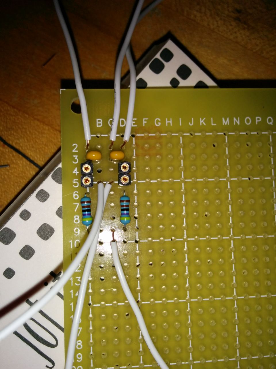
Are you asking about the capacitors in my filters? These ones?
If so, them from what I recall (again, I'm a software guy, so I didn't design this circuit), the two wires at the top corners are the signal inputs, and the two wires in the center are signal outputs. I think the wire at the bottom is +5, making the blue resistors into "pull-up resistors". The wire at the top is ground, and connects to the two inboard pins on the capacitors. The two black sockets are so we could experiment with different size resistors to tune the frequency at which it cuts stuff off. I don't remember what resistors (or capacitor values, for that matter) are in there right now, it turned out to work fine (amazingly well, in fact) with the initial setup, so we didn't bother to try anything else.
It's a pair of low pass "RC filters", which allow low frequency signals through but block high frequency signals. Wikipedia article here: https://en.wikipedia.org/wiki/RC_circuit
Stock, the cam & crank sensors come into the ECU on pins 2H and 2J. I re-pinned them in my extension harness to use 2M and 2O, which are normally EGR control wires and are thus unused in the MS3. The two signal input wires to my filters are connected to those two pins. Ground, +5, and the two signal output wires are connected to the connector stack (and thus to the MS3 CPU board). I'm not sure if there are distinct signal vs ground wires in the ECU harness or not, or if so which of the three ground pins on connector 3 are which.
Thank you, Ian. Have you gotten yours running again?
EDIT: I find the layout of the 2000 wiring diagram easier to understand. Same info, same harness, but presented in a different format.
Mine never really stopped running, in fact it was somewhat difficult to reproduce the problem. I'm about 90% confident it's a bad cam sensor, but I want more data. I'm putting together an Arduino so that I can do composite tooth logging to an SD card and have it on all the time.
Any thoughts on using opto-in for the Crank and Cam vs the VR inputs with the trim pots. As I keep seeing comments on how to adjust the pots, I presume that is what most people are using.
I'm still going to try to find if I have a ground other wiring problem, but I'm wondering if I should switch that out. I understand the V3.57 boards come populated with both inputs. Seems to me, swapping them makes more sense than putting in a low pass only input.
I have measured the Crank sensor output (not in car). With 5-16 V Black to Red, the blue wire outputs a nice square wave at 0.75V, when a steel object passes the face of the sensor. A lower output than I would have guessed.
EDIT: According to 2016 posts I see that I was not measuring the sensor correctly. Now I understand why there is a pulp to VCC in the schematic.
EDIT: Removed tag to Joe.
Last edited by DNMakinson; 11-25-2016 at 01:57 PM.
I fixed the problem, though I do not yet know the root cause.
One of the changes I had made was to go from analog O2 input to the Serial-CAN input. This is with MS3-Basic, MSLabs CAN O2 Module, Innovate LC-2 controller.
So, I reverted back to the analog input of AFR. No change.
Then I cut all 4 wires between the CAN Module and the MS. I have not had a sync fault on a running engine since then.
What I don't know is what was wrong with the set-up; but I'm not sure I care. Since I had worked out the needed offsets, I'm thinking that adding the digital interface was gilding the lily.
Damn. That sucks. I've got a near identical setup (MS Labs Basic MS3 90-93, MS Labs WBO2 CAN Module, Innovate LC-2) and I've got the same problem: random sync loss (error #2: missing tooth at wrong time). I'll have to run the composite logger for longer to capture one of these many sync loss errors (80+ in one 35 min driving session) as the only composite log I have is too short and everything there is looking just fine. I'll also have to study the setting up manual where they talk about different Noise Filtering options. Someone recommended I try testing whether a pullup resistor might fix my sync loss error by making a jumper wire with a 1k ohm resistor in it and connect it between pins 2D (Tach Out) and 3N (+5Vref).
Update: My random sync loss errors appear to have finally gone away after installing a new MS Labs CAN Wideband Module. I got this new one from Trackspeed Engineering, who shipped very fast. Thank you! The new module is an updated design. Not sure what was wrong with my original unit but it was definitely defective, just like what DNMakinson experienced. Disappointingly, Reverant ignored my email requests for product support and troubleshooting assistance with his defective CAN Wideband Module. Because of this disrespect, I was hesitant to reward him with more business. But no one else makes such a tidy product that promises to do what his CAN Wideband Module does. Sometimes you just have to pay to play. From now on, I suggest you skip Reverant and deal with his US distributor TSE instead. Onward and upward!
I do apologize for missing your previous emails. Feel free to send me back the module for reprogramming to the latest firmware (1.0.4), as unfortunately you can't upgrade the firmware on the module yourself.
I do apologize for missing your previous emails. Feel free to send me back the module for reprogramming to the latest firmware (1.0.4), as unfortunately you can't upgrade the firmware on the module yourself.
Can you fix my CAN module so that it plays well with my MS3 V2? If so, please PM your shipping address.
I'd like to use the module, but have lived with analog input for a couple of years now.
 11-17-2016, 09:11 PM


 0
0