When you click on links to various merchants on this site and make a purchase, this can result in this site earning a commission. Affiliate programs and affiliations include, but are not limited to, the eBay Partner Network.
Newly built ms3x using trubokitty. Cranks, composite log empty, no rpm, no start.
Hi all, I am having an issue with my newly built ms3x for a 99 nb. Ms3x powers on and connects to laptop. All sensors configured and appear to be working.
When cranking car gets no spark. Ran a composite log and noticed there is no crank signal, cam signal, or rpm.
Adjust r32 r56 and r11 multiple times using trubokitty.com as a reference with the same result. Car starts and runs with stock ecu. Pretty sure I may have messed something up. My question is where do I check voltage when adjusting the pots r56 and r11? What else should I look at on my board that may cause this issue. I have searched for here this issue and noticed people saying they are checking voltage but just not sure where.
Is there anyone near the bay area California that would be wiling to troubleshoot and fix whatever I may have messed up. I would be more than happy to pay for services. At this point I am lost.
When you made the harness adaptor, you wired it up as viewed from one side, and not the other? One of the views is a bit confusing with how it is viewed on the pinout.. you might have that completely mirrored to what it needs. Make sure to read the text in the margins
Thank you for the input. I double and tripled checked my harness going by the numbers that were labeled on the db connectors. I believe that would be the correct orientation and my other sensors are working properly.
Also verified there were no bridges between q22 and q23.
I found a diagram of the vr circuit and verified I have all components needed that were installed. I also checked for any blown traces. Is it possible one of the components is just bad?
I would highly recommend to supply an image of your harness, both sides (car and ECU), to confirm
I have seen at least 5 people on this forum that built their own that said the same thing until they showed an image and they had their inputs mirrored on a plug
People try to help, and they ask for you to supply a specific thing, in my last post, "please get pictures of both ends"
You refusal to supply a picture of the other end because of your insistence that it is correct just now adds more steps to try to fix it. Your thing is broken, so when people try to help and you flat out refuse to help them help you, make sure to look in a mirror to figure out why it continues to stay broken.
The pictures are to confirm, you flat out refuse to even allow us to rule that out as an issue now because you wont take some pictures.
I had literally started to take my harness apart so I could compare mine to yours directly when I got the email that you posted with lack of images I asked for so I could compare. I put mine back together because if you dont even want to help yourself, I am not going to bother.
Your thread is turning into one like this, where the OP kept doing everything completely opposite and refused to take the advice of the people trying to help them. https://www.miataturbo.net/megasquir...e-help-102637/
I did not give any push back and tried to respond as quick as I could for you since you were on. I never said I was not going to get pictures I was just not able to get them right now at 11pm. Not once did I "flat out refuse". I thank you for trying to help and will get those pictures as soon as I can. I also have never done anything completely opposite and have tried to give as much info as possible. Sorry if you felt like I was being lazy or inconsiderate neither were my intentions.
I will try 8 and 9 instead of 9 and 10. I was following this diagram on trubokitty for pinouts. And again I thank you and appreciate your willingness to help.
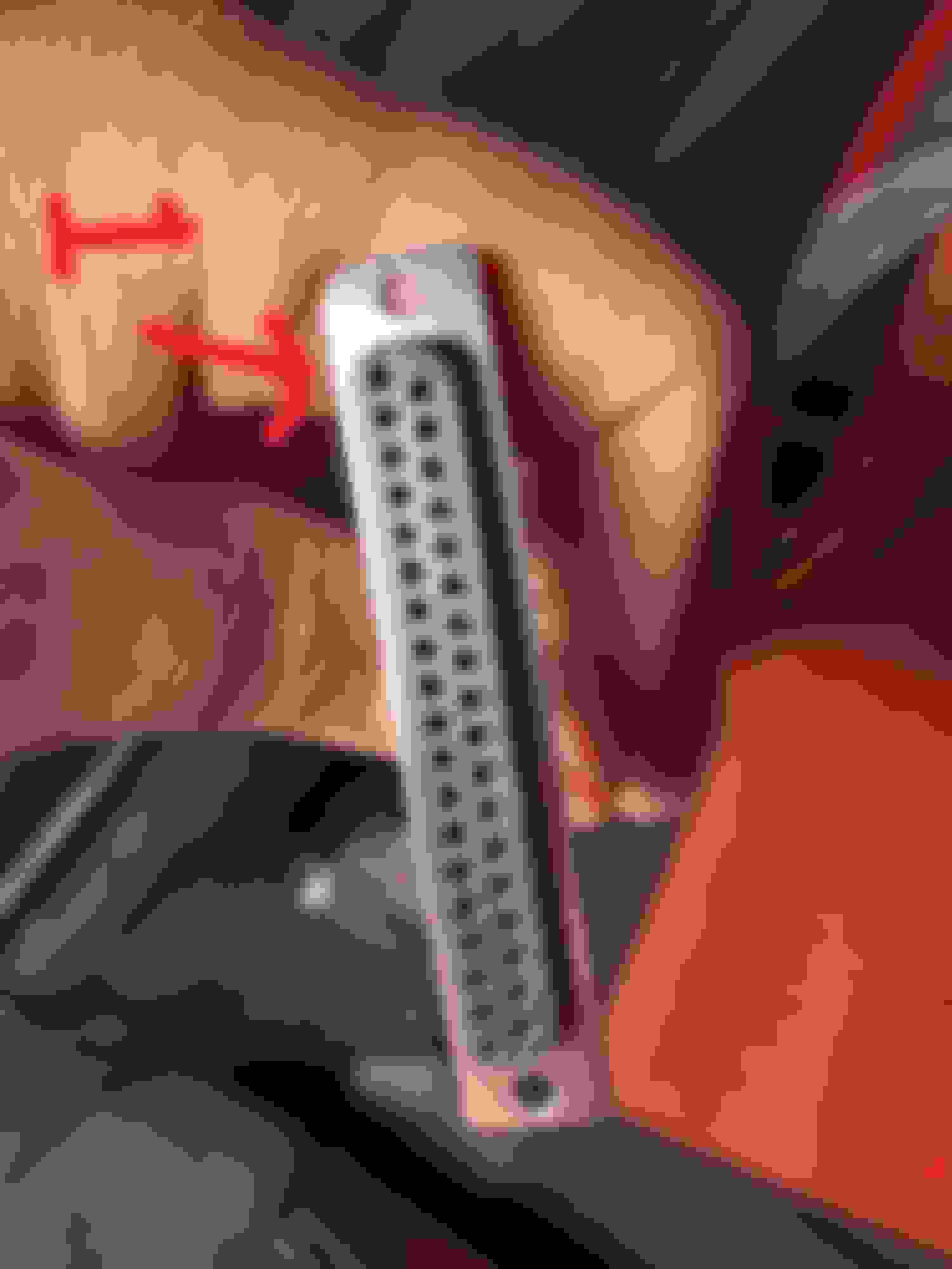
Ok just so I'm on the same page I was going by the way the connector had the pins numbered. I should not use that and count looking at the plug from the front? When looking at the diagram that way It def looks like I mirrored it. Just want to make sure I fully understand this. I am attaching a picture showing the pin labeled 1 and that is where I started originally.
All harness are correct. Again checked over them again.
When testing for voltage at u7 pin 3 I am only getting .60 volts. After trying to adjust r56 ny turning them both ways the voltage does not change. Pretty sure this is my issue as I need to get it to at least 2.5v.
Does any one smarter than me have an idea on how I can troubleshoot this down further or have an idea of what may be the cause? Thank you.
 04-17-2021, 02:42 AM


 0
0