Tried to start for first time = no go
#22
Senior Member
Thread Starter
iTrader: (2)
Join Date: Aug 2005
Location: Granbury, TX
Posts: 562
Total Cats: 1
Could there be any settings on megatune im doing that would make it not fire?
What should my spark advance be reading at idle (when i have the stock ecu running the spark) i think its set really high but im not sure
What should my spark advance be reading at idle (when i have the stock ecu running the spark) i think its set really high but im not sure
#24
Boost Czar


iTrader: (62)
Join Date: May 2005
Location: Chantilly, VA
Posts: 79,493
Total Cats: 4,080
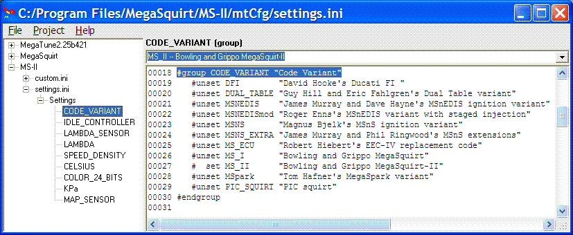
yeah, under settings > codebase
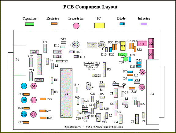
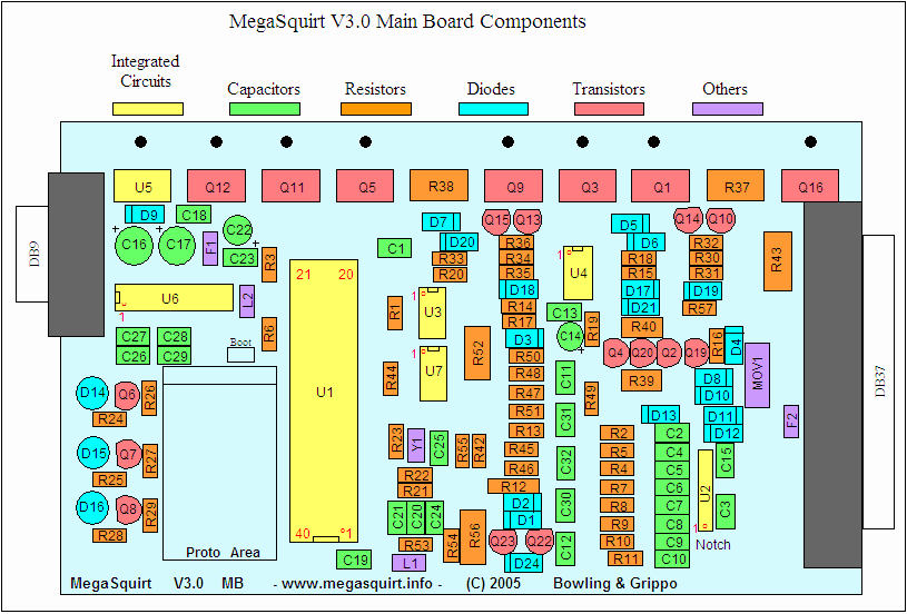
the LED guys should have spark A and spark B, on my MS3 board I have LED17 as A and LED19 as B. If those aren't correct spark wont work, sadly we are reaching the end of my limited knowledge....
greenday, yours look like d18 and d19, not sure if your output settings reflect that...
the LED guys should have spark A and spark B, on my MS3 board I have LED17 as A and LED19 as B. If those aren't correct spark wont work, sadly we are reaching the end of my limited knowledge....
greenday, yours look like d18 and d19, not sure if your output settings reflect that...
#25
Senior Member
Thread Starter
iTrader: (2)
Join Date: Aug 2005
Location: Granbury, TX
Posts: 562
Total Cats: 1
yeah, under settings > codebase
the LED guys should have spark A and spark B, on my MS3 board I have LED17 as A and LED19 as B. If those aren't correct spark wont work, sadly we are reaching the end of my limited knowledge....
greenday, yours look like d18 and d19, not sure if your output settings reflect that...
the LED guys should have spark A and spark B, on my MS3 board I have LED17 as A and LED19 as B. If those aren't correct spark wont work, sadly we are reaching the end of my limited knowledge....
greenday, yours look like d18 and d19, not sure if your output settings reflect that...
#28
Senior Member
Thread Starter
iTrader: (2)
Join Date: Aug 2005
Location: Granbury, TX
Posts: 562
Total Cats: 1
One more thing, wich doesnt really have to do with this, but on the easytherm program, on the dropdown window for selecting what com port to use, it only lets me select COM1-4, when i need to use COM5, and when i type it in manually it says error, any ideas?
#29
Boost Czar


iTrader: (62)
Join Date: May 2005
Location: Chantilly, VA
Posts: 79,493
Total Cats: 4,080
yeah, see i dunno. you have the v2.2 board....im just looking at megamanual at the diagram and those outputs are d18 and d19....

but look on the v3 board (mine), and you see D14 D15 and D16


but look on the v3 board (mine), and you see D14 D15 and D16

#30
Senior Member
Thread Starter
iTrader: (2)
Join Date: Aug 2005
Location: Granbury, TX
Posts: 562
Total Cats: 1
Yeah i totally see what you are talking about, maybe the software im using is wrong or something? I wish fulltilt would get around to getting on hes the one that built it and im sure he would have a good idea
#32
Boost Czar


iTrader: (62)
Join Date: May 2005
Location: Chantilly, VA
Posts: 79,493
Total Cats: 4,080
dunno, but i would think there would be a variant, since you have outputs like JPx and my board has ones labeled JSx
there is code variant in the configuator, but im not sure what youd should or should not be using....i have VERY limited knowledge...

there is code variant in the configuator, but im not sure what youd should or should not be using....i have VERY limited knowledge...
#34
Boost Czar


iTrader: (62)
Join Date: May 2005
Location: Chantilly, VA
Posts: 79,493
Total Cats: 4,080
i had the same problem with my spark outputs....which is what i think your problem might be. It was built on a V3 board according to DIY's writeup, however it didn't spark....it took all day, but i was able to figure it out. for one the spark outputs were reveresed on the board (not builders fault), but for some reason DIY's resistors on the spark output and the pin location didn't give a spark....
#35
Senior Member
Thread Starter
iTrader: (2)
Join Date: Aug 2005
Location: Granbury, TX
Posts: 562
Total Cats: 1
i had the same problem with my spark outputs....which is what i think your problem might be. It was built on a V3 board according to DIY's writeup, however it didn't spark....it took all day, but i was able to figure it out. for one the spark outputs were reveresed on the board (not builders fault), but for some reason DIY's resistors on the spark output and the pin location didn't give a spark....
#37
Senior Member
Thread Starter
iTrader: (2)
Join Date: Aug 2005
Location: Granbury, TX
Posts: 562
Total Cats: 1
Yeah i know.. oh well, i looked back at what fulltilt did to make spark work:
I removed Q9 and Q10, replaced R25 and R28 with 330 ohm, and ran a wire from the side of the resistor that went to the transistor to X12 and X13. I think that was what King meant by "the top of resistor R25". Hooked them to the brown wires going to my ignitor. It tried to run backwards, so I reversed them, and it ran but only on two cylinders I think. I'll keep trying, but I thought I'd lay out my steps in case something jumped out at anyone.
then this is what he did to fix it:
I'M SPARKING, I'M SPARKING!!!!!!! We threw an o-scope on it and found a signal on the processor side of the resistor, and none on the led side. Came back inside and pulled it apart and apparently I kluged (sp?) the removal of one transistor. The remaining solder gunk was making a short. Cleaned it up and it runs like a champ. When I get home, that AFM is GONE!!!
but im not sure if thats whats wrong with this or not
#38
Senior Member
Thread Starter
iTrader: (2)
Join Date: Aug 2005
Location: Granbury, TX
Posts: 562
Total Cats: 1
Well i took mine apart to look at it, looks like he removed q9 and q11 instead of q10 like he said on the post above.. what do you think about that? did he accidently do the wrong one?
#39
Boost Czar


iTrader: (62)
Join Date: May 2005
Location: Chantilly, VA
Posts: 79,493
Total Cats: 4,080
the removed diodes look right, id try the "wrong side of the resistor" thing....that was exactly my problem...I plain removed the two reisistors and soldered the outputs to the pin that gave the correct output.
bet you're seeing something very similar....
put the two wires on the other side of the resistors and see if you get spark then...if it does get spark but doesnt catch, kinda pops and combusts, reverse them and put a on b & b on a....then it should catch.
bet you're seeing something very similar....
put the two wires on the other side of the resistors and see if you get spark then...if it does get spark but doesnt catch, kinda pops and combusts, reverse them and put a on b & b on a....then it should catch.
#40
Senior Member
Thread Starter
iTrader: (2)
Join Date: Aug 2005
Location: Granbury, TX
Posts: 562
Total Cats: 1
the removed diodes look right, id try the "wrong side of the resistor" thing....that was exactly my problem...I plain removed the two reisistors and soldered the outputs to the pin that gave the correct output.
bet you're seeing something very similar....
put the two wires on the other side of the resistors and see if you get spark then...if it does get spark but doesnt catch, kinda pops and combusts, reverse them and put a on b & b on a....then it should catch.
bet you're seeing something very similar....
put the two wires on the other side of the resistors and see if you get spark then...if it does get spark but doesnt catch, kinda pops and combusts, reverse them and put a on b & b on a....then it should catch.


