Modifying Brainy MS board for vTPS - think I have locations wrong
 08-26-2011, 11:55 PM
#1

Bought an MS from Brainy a couple months ago, and he forgot that I was going to be running a vTPS in my 1991 na6, so it wasn't hardware modded for it.
He told me what to do - run a jumper wire from a 5v source to pin 1N, and remove the 1k resistor between 4L and 4D.
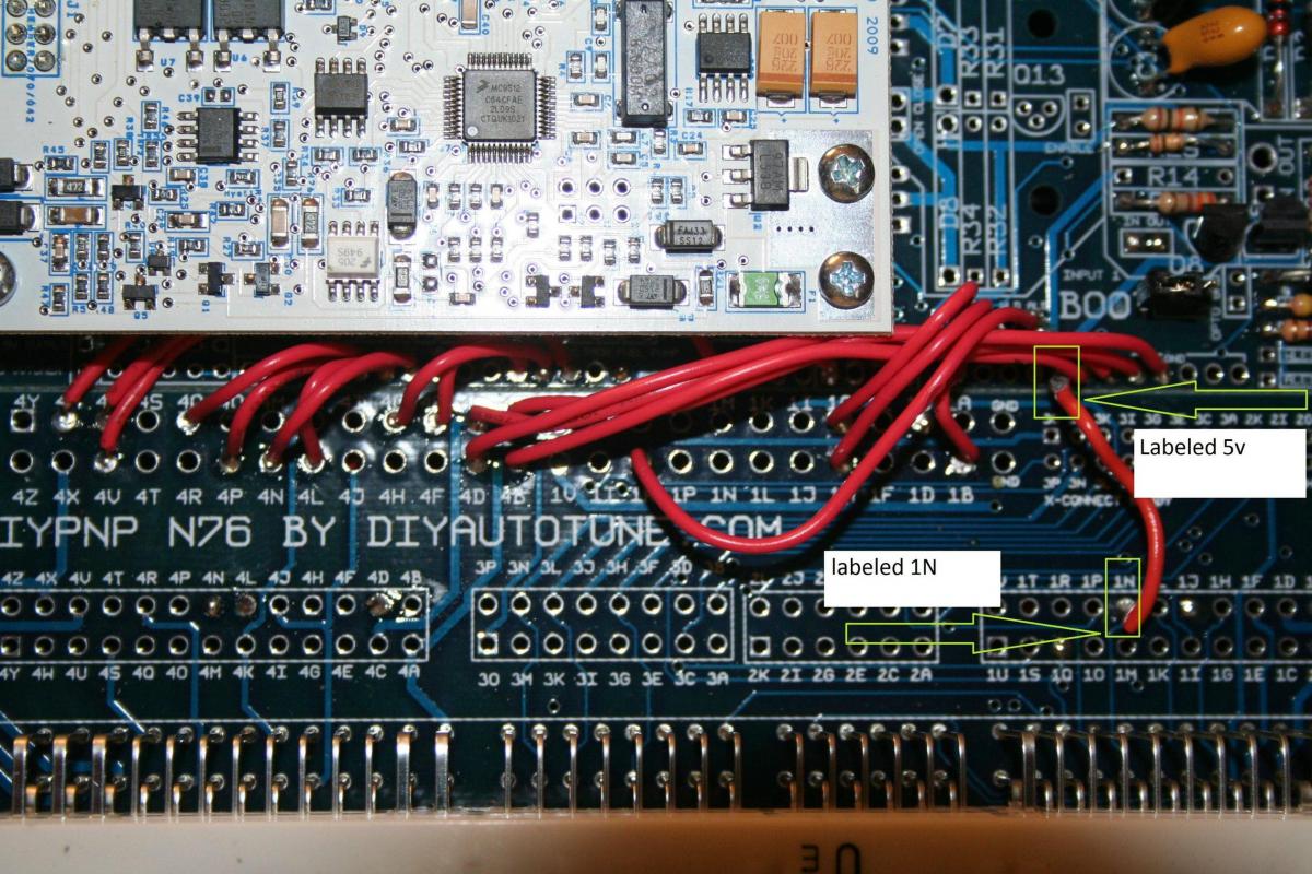
Above pic shows my jumper wire soldered in from a point labeled "5v" on the board to the pin labeled "1N" on the bottom of the board. The 1k resistor was snipped off the pins labeled 4L and 4D in the lower left.
The problem I'm having is that when I try to calibrate the TPS in tuner studio, it registers the same value with the throttle open or closed. I've ruled out miswiring the oem tps wires to the 4-pin tps by literally trying all 16 permutations of wire locations. I would get different values in TS, but they would still match between open/closed, so it wasn't seeing the change in throttle postion.
That's why I am now wondering if I've got the hardware mods to the MS wrong.
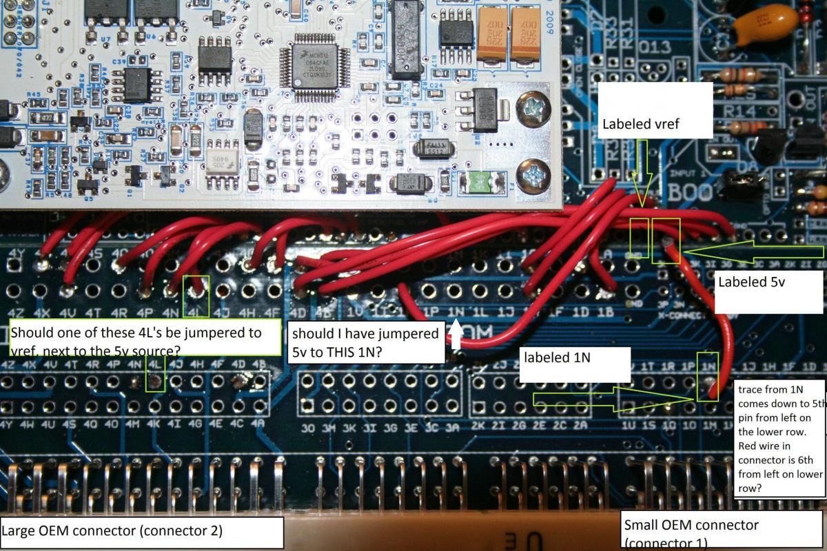
Specifically, the "1N" I soldered to on the MS. I'm wondering if I should have soldered to the "1N" that's right below the white microsquirt module, where all of braineack's jumper wires were. See pic below:
I also found some doubt in reading Joe Perez's writeup on modifying the MS for a variable TPS. Joe says:
I'm not sure which pins "pin 26" and "pin 22" joe is referring to, but I'm guessing they are from an older MS PCB. Pin 22 on his version board is probably the +5v source, and it connects to 1N, which should correspond to the red wire. That would match what Braineack said to do.
The other connection Joe says to make, Braineack doesn't. That would be connecting "pin 26 (vref)" to 2L, which should correspond to the green/white wire on the larger OEM ECU connector. Where the larger OEM ECU connector goes on the MS, the pins are labeled "4(letter)" rather than "2(letter)" so presumably I would be looking for "4L". 4L is where one leg of the 1k resistor went when the MS was shipped, set up for running without TPS.
So I'm unsure as to whether I should solder a jumper from the pin marked "vref", right next to the one marked "5v", to either pin 4L along the same row as I currently have the jumper for 1N, or the 4L along the row under the microsquirt module where Braineack's jumper wires are. Or if I don't have to do it at all. I'd think Braineack would have mentioned it if it had to be done.
Another thing I am concerned about is whether the number/letter markings on the MS PCB are accurate, IE, that they correspond to the same number/letter on the OEM miata ECU. For example, if I follow the trace that connects the point "1N" I soldered the jumper wire to, to the actual pin where the connector clips onto, I find that the trace connects to the 5th pin from the left on the lower row. On the OEM ECU connector, the Red wire is actually the *6th* pin from the left on the lower row.
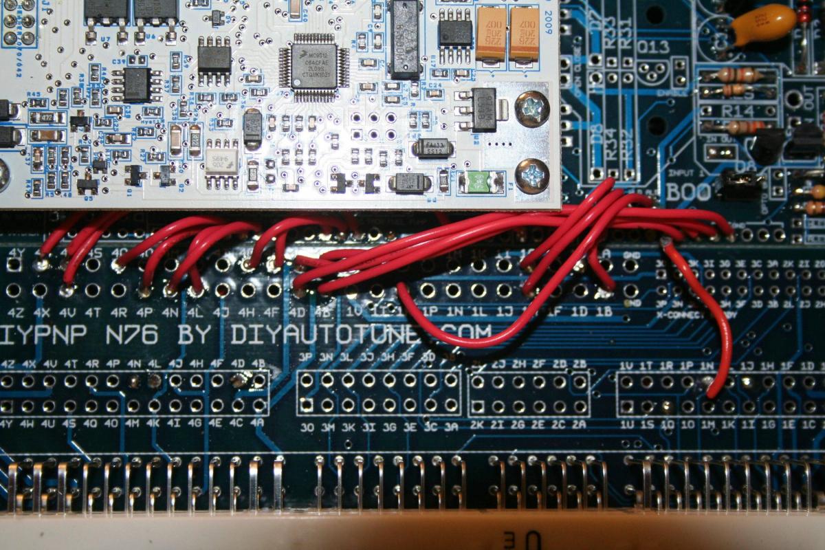
Sorry if all this is confusing. If anyone has this revision megasquirt PCB, that has been modded for an na8 vTPS, feel free to use this blank PCB picture to draw in MSpaint where the jumper wire(s) should go. I think there used to be such pictures in the various vTPS threads I found by searching, but the threads were all old enough that the picture links no longer worked. A picture would help to avoid confusion brought on by writing "1N" since there are multiple spots on the PCB labeled 1N. Pic:
He told me what to do - run a jumper wire from a 5v source to pin 1N, and remove the 1k resistor between 4L and 4D.
Above pic shows my jumper wire soldered in from a point labeled "5v" on the board to the pin labeled "1N" on the bottom of the board. The 1k resistor was snipped off the pins labeled 4L and 4D in the lower left.
The problem I'm having is that when I try to calibrate the TPS in tuner studio, it registers the same value with the throttle open or closed. I've ruled out miswiring the oem tps wires to the 4-pin tps by literally trying all 16 permutations of wire locations. I would get different values in TS, but they would still match between open/closed, so it wasn't seeing the change in throttle postion.
That's why I am now wondering if I've got the hardware mods to the MS wrong.
Specifically, the "1N" I soldered to on the MS. I'm wondering if I should have soldered to the "1N" that's right below the white microsquirt module, where all of braineack's jumper wires were. See pic below:
I also found some doubt in reading Joe Perez's writeup on modifying the MS for a variable TPS. Joe says:
"At the Megasquirt, connect pin 26 (Vref) to the green / white wire at position 2L of the ECU harness, and connect pin 22 (TPS) to the red wire at position 1N of the ECU harness."
The other connection Joe says to make, Braineack doesn't. That would be connecting "pin 26 (vref)" to 2L, which should correspond to the green/white wire on the larger OEM ECU connector. Where the larger OEM ECU connector goes on the MS, the pins are labeled "4(letter)" rather than "2(letter)" so presumably I would be looking for "4L". 4L is where one leg of the 1k resistor went when the MS was shipped, set up for running without TPS.
So I'm unsure as to whether I should solder a jumper from the pin marked "vref", right next to the one marked "5v", to either pin 4L along the same row as I currently have the jumper for 1N, or the 4L along the row under the microsquirt module where Braineack's jumper wires are. Or if I don't have to do it at all. I'd think Braineack would have mentioned it if it had to be done.
Another thing I am concerned about is whether the number/letter markings on the MS PCB are accurate, IE, that they correspond to the same number/letter on the OEM miata ECU. For example, if I follow the trace that connects the point "1N" I soldered the jumper wire to, to the actual pin where the connector clips onto, I find that the trace connects to the 5th pin from the left on the lower row. On the OEM ECU connector, the Red wire is actually the *6th* pin from the left on the lower row.
Sorry if all this is confusing. If anyone has this revision megasquirt PCB, that has been modded for an na8 vTPS, feel free to use this blank PCB picture to draw in MSpaint where the jumper wire(s) should go. I think there used to be such pictures in the various vTPS threads I found by searching, but the threads were all old enough that the picture links no longer worked. A picture would help to avoid confusion brought on by writing "1N" since there are multiple spots on the PCB labeled 1N. Pic:

Reply
 0
0

0
08-27-2011, 11:02 AM
#3
I've got the wires where they are supposed to go on the TPS, to confirm that, I used a multimeter to read their resistance while actuating the throttle body.
-With my multimeter's positive probe on the red wire, neg probe on black/grn wire, get a reading of 0.00 with throttle plate closed, goes up to 4.14 as soon as the throttle plates are cracked, stays 4.14 all the way to WOT.
-With positive probe on green/white wire, neg probe on black/grn, read .52 with throttle closed, and raised linearly to 3.62 with the throttle at WOT.
So that tells me that I've got the Idle switch signal going down the Red wire, the TPS signal going down the green/white wire, and the black/grn is the ground. That's correct, I believe.
Yet, in tuner studio, when I got to calibrate the TPS, I get an initial (closed) value of 13, and a WOT (open) value of...13.
That's the problem, and I have no idea why TS isn't seeing the difference between closed and WOT.
Reply
0
0
08-27-2011, 11:26 AM
#4
Boost Czar


iTrader: (62)
Join Date: May 2005
Location: Chantilly, VA
Posts: 79,490
Total Cats: 4,079
the red wire doesn't sound like it's going to the right spot? it should always be at 5v no matter what throttle position. it's just the power source for the variable resistor.
you need the 5v wire to go to the 5v input on the tps.
but when you measure the green/wht wire that sounds exactly what it's supposed to see. unsure why tunerstudio isn't seeing the voltage change...can you confirm that voltage at the DIYPNP itself?
you need the 5v wire to go to the 5v input on the tps.
but when you measure the green/wht wire that sounds exactly what it's supposed to see. unsure why tunerstudio isn't seeing the voltage change...can you confirm that voltage at the DIYPNP itself?
Reply
0
0
08-27-2011, 03:48 PM
#5
Ah. I was measuring resistance of the red wire when I should have been measuring voltage.
I took the cover off the MS and hooked it up that way so that I could measure the pins with everything powered up.
-I do measure 5v on the red wire, both on the MS pcb @ 1N, and at the TPS.
-I do measure the resistance change on the green/white wire, both at pin 4L on the MS pcb, and at the TPS connector, when the throttle is actuated.
-I measured continuity of the black/grn wire from the tps connector to pin 1R @ the ms pcb, and got a resistance reading of 168, where I should have seen 000 or 001. So I ran a new wire from the tps connector to the ecu connector, and after that I have 000 continuity, so that's good.
Now tuner studio isn't even showing a TS value of 13 though, it's showing 1028, which means it's not reading anything at all.
So I've proven that the MS pcb is getting the tps resistance, that there is continuity with the ground from the pcb to the tps, and that the pcb and TPS are both seeing 5v. Tunerstudio should be able to see what's going on...
The only things I can think of, are that if I do a continuity check between the red and green/white wires, I get a value of 470. I'm not sure there should be any continuity between the red and green/white wires.
The only two things I can think to do are to hook up the na8 tps and see if that will give a reading in tuner studio, or secondly, to run new wires for green/white and red, to make sure there there isn't a melted section somewhere in the loom where the two wires are touching.
Reply
0
0
08-27-2011, 04:26 PM
#6
well ****.
I decided to take the slightly oddball toyota tps out of the loop for testing purposes, just to further isolate what the root cause is here.
Here's the experiment I just ran:
I took an na8 tps, and I hooked it up using the spare na8 tps pigtail I got with the TPS. To take potential problems with my 91's wiring harness out of the loop, I connected the na8 tps pigtails using new wires, run directly to the MS pcb, attached at the pcb using tiny alligator clips. So the grn wht wire of the pigtail was clipped onto the 2L point on the pcb, the red/black wire was clipped onto 1N, the black/grn wire I kept in the oem ecu connector since I just ran a new wire for it a couple hours ago, and it's def. good.
Before I tried tuner studio, I turned the ignition to "on" and used the multimeter to test my connections and make sure they were good. I verified that 5v was getting to the tps (well it was actually slightly under 5v, which I'd attribute to the alligator clip rather than soldering) by attaching the negative probe to chassis ground, and the positive probe to the red wire. Then measured the resistance with the positive probe on the green/white wire and the negative probe on the black/grn wire. Successfully measured a resistance change as I manually actuated the na8 tps.
So, I should have seen tuner studio get values for idle and WOT throttle positions. Only I still don't. Both TS values read 1023 (I said 1028 in the last post but was mistaken, 1023 is what TS reports when it's not reading a signal.)
So I'm boned, it seems. All my hardware is set up as it should be, and I still cannot get a reading. Without a variable TPS there is no hope in hell of getting my ITB's to work properly.
Reply
0
0
08-27-2011, 06:33 PM
#7
Boost Czar
iTrader: (62)
Join Date: May 2005
Location: Chantilly, VA
Posts: 79,490
Total Cats: 4,079
you need to measure for voltage back to the MS; the input into 4L should be 0v when no throttle input and close to 5v when WOT.
if TS is showing 1028, that's pretty much showing that you're sending 5v straight into the input.
the TPS is a crazy simple device: There's 5v on one side, and ground to the other side of a variable resistor. When you move the throttle you change the resistance to ground, the greater the resistance, the more voltage that dumps into the tps input back to the ecu.
the best way to find the correct pins on your TPS is the following:
The resistance between the 5v and ground pins will remain constant.
The resistance between the ground and signal pins will be low with the throttle closed and high with the throttle wide open.
The resistance between the 5v and signal pins will be high with the throttle closed and low with the throttle wide open.
Reply
0
0
08-29-2011, 11:45 PM
#8
the best way to find the correct pins on your TPS is the following:
The resistance between the 5v and ground pins will remain constant.
The resistance between the ground and signal pins will be low with the throttle closed and high with the throttle wide open.
The resistance between the 5v and signal pins will be high with the throttle closed and low with the throttle wide open.
so first, I'll attempt the method with the na8 tps. It's well documented what pins are what on that, so if I'm ******* up the procedure, that will be obvious to all but me.
The resistance between the 5v and ground pins will remain constant.
- same for
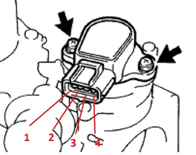
neg probe: pin 4 pos probe: pin 1
So the ground and 5v pins are 1 and 4 in some combination not clear yet.
The resistance between the ground and signal pins will be low with the throttle closed and high with the throttle wide open.
neg probe: pin 4 pos probe: pin 2
So that identifies ground as pin 4, signal as pin 2, and since 5v was either 1 or 4, it must be pin 1, leaving only pin 3 to be IDL switch.
Still, will carry through last test.
The resistance between the 5v and signal pins will be high with the throttle closed and low with the throttle wide open.
neg probe: pin 1 pos probe: pin 2
So let's try this little bastard in my car - since I want to keep all variables to a minimum, I am not using the OEM harness, I am running wires directly to the MS board using gator clips.
pin 1 (5v) will not be used
pin 2 (TPS signal) will be connected to 4L
pin 3 (Idle)will be connected to 1N
pin 4 (ground) will be connected to pin 1R
I've tested continuity from board to tps to assure there are no connection issues.
ignition to on, start up tuner studio.
First thing that happens is that I get a popup that says I have a configuration error, basically that the controller has a different config than TS does. This only started popping up when TS found an update on friday or saturday. I haven't written to the controller since I completed all other setup steps aside from the TPS. It's appeared at every startup since I updated tuner studio.
Carrying on, I open the calibration window, and get current - and I get 1023.
Taking a voltage reading of 4L at this time shows 5.05v
When I manually actuate the TPS to wot (I don't have it connected to the ITBs at this point), the voltage at 4L drops to 0.02v. But clicking get current on either open throttle, or closed throttle, both read 1023. When I read the voltage at 1N, it is at 5.06v regardless of where the TPS is in its sweep.
So that's where I'm at. Of course I tried the same process with the toyota TPS, but I had the same results. Falling voltage from 5v to 0v on 4L, constant 5v on 1N no matter the tps position, and a solid 1023 in tuner studio calibration.
I also cracked the tps's open. Dumb, maybe, but I had to see what was inside the ******* and how it differed. Putting them back together I got no change in readings anyways.
Here's how they differ:

That's the actual trace patterns underneath the tops of the TPS's. Basically they are mirror images, which makes some sense, as the direction of movement for the TPS arms is clockwise for the NA8 and counterclockwise for the ae101.
Reply
0
0
08-30-2011, 07:42 AM
#9
Boost Czar
iTrader: (62)
Join Date: May 2005
Location: Chantilly, VA
Posts: 79,490
Total Cats: 4,079
you're still not connecting it right.
why do you keep insisting on putting 5v on the idle switch on not on the 5v input?
and why would you connect ground to 1r? that's the fan relay switched ground.
looking at the na8 tps. it should connect as the following:
pin 4 - ground. connect to stock bg/lg wire at the oem TPS connector (grounds at fuel rail)
pin 3 - NOTHING
pin 2 - TPS out. Connect to stock lg/wht wire at the oem connector. (4L)
pin 1 - 5V in. Connect to stock red wire at the oem connector. (1N)
since you opened them up you probably damaged the sweeper brush and they'll never work properly again.
Reply
0
0
08-30-2011, 06:38 PM
#10
had thought the 5v was the pin not in use, rather than the idle pin.
Set up the wires as directed and used the oem loom this time.
Now when calibrating, closed is 2, and open is 2. Voltage at 4L is 0.00 closed, rising to 4.56 open.
As I was still getting the boost controller pin conflict message on startup with 1.13, and found no conflict, I downgaded to v1.04 and no longer receive the conflict message.
Tps calibration was unaffected though, still 2/2.
Reply
0
0
08-31-2011, 06:23 PM
#12
sorry for the late reply -
Guessing mmsq was a phone typo, and you meant msq.
In the file/project properties/settings page, there was no selection for boost control with this Ecu definition, MS2Extra Serial310. The only two changes I made among those selections were setting o2 to wideband, and microsquirt_module to activated.
As I said, the boost control pin error message has disappeared after reverting to tunerstudio 1.04, but perhaps you're wondering if there is still a conflict between the boost control pin and tps.
opened my msq in wordpad and searched for "pin". Came up with only the following:
<constant name="boost_ctl_pins">"Fidle"</constant>
<constant cols="1" digits="0" name="rmt_psInitValue" rows="8">
0.0
0.0
0.0
0.0
0.0
0.0
0.0
0.0
</constant>
otherwise -
Verified 5v is getting to the TPS, and that there is continuity between black/grn @ tps and the fuel rail ground.
I reversed the wires at the TPS connector and hooked up the Toyota TPS, with identical results to the NA8 tps - got 6 for closed and 6 for open.
attaching the .msq just in case
Reply
0
0
08-31-2011, 06:35 PM
#13
Boost Czar
iTrader: (62)
Join Date: May 2005
Location: Chantilly, VA
Posts: 79,490
Total Cats: 4,079
(Posting from my phone.)
Well boost control set to fidle will cause a conflict...yours should be set to Pt7. Clear the conflict and see if tps will register
Well boost control set to fidle will cause a conflict...yours should be set to Pt7. Clear the conflict and see if tps will register
Last edited by Braineack; 09-01-2011 at 07:39 AM.
Reply
0
0

Thread
Thread Starter
Forum
Replies
Last Post
Zaphod
MEGAsquirt
47
10-26-2018 11:00 PM
StratoBlue1109
Miata parts for sale/trade
21
09-30-2018 01:09 PM


