Megasquirt vs Microsquirt for my rebuild.
 09-06-2012, 11:28 AM
#1
Elite Member
Thread Starter
iTrader: (8)

Join Date: Dec 2008
Location: Kingston, Ontario
Posts: 2,910
Total Cats: 51
All that I seem to find online is that the Microsquirt is similar to megasquirt 2 but for smaller applications.
The Map sensor being external is fine for me assuming that you can adjust the parameters required to run different sensors.
What kind of actual differences would there be in a build where I will be building a complete engine and chassis wiring harness in a chassis up race build where i wont need the ECU to control everything like fuel pumps and idle valves...
I found this link and it seems like it would work totally fine i just dont see why its not used more in the MT area...
Megasquirt Product Comparison
Matt

Reply
 0
0

0
09-06-2012, 12:02 PM
#3
Elite Member
Thread Starter
iTrader: (8)
Join Date: Dec 2008
Location: Kingston, Ontario
Posts: 2,910
Total Cats: 51
same software and all?
So i can use the wealth of knowledge here and the basemaps etc just plug them in and (presuming i wired the engine correctly) go to town?
Unreal. This is perfect!
So i can use the wealth of knowledge here and the basemaps etc just plug them in and (presuming i wired the engine correctly) go to town?
Unreal. This is perfect!
Reply
0
0
 09-13-2013, 12:05 PM
#5
Elite Member
Thread Starter
iTrader: (8)
Join Date: Dec 2008
Location: Kingston, Ontario
Posts: 2,910
Total Cats: 51
I want to bump this back up....
I am looking at the microsquirt info again and im looking at the following:
So what would this mean for running a miata engine? would stock injectors be fine if i wanted to use them for the time being?
I am looking at the microsquirt info again and im looking at the following:
1.The fuel injector drives will max out at 5 amps each, enough to drive one low-impedance (or 4 high-impedance) injector per bank. To get everything to fit without lots of heat sinking, MicroSquirt uses the ST VND5N07 from STMicroelectronics to drive the injectors. This is not a 'peak and hold' driver, but it does clamp the current at 5 amps, so it can be used with one low-impedance injector per bank, however the close time may be a tad higher (or you can use resistors). For up to 4 high-impedance injectors per bank, it should work fine. For example, for motorcycle use MicroSquirt will be perfect!
Reply
0
0
 09-13-2013, 05:28 PM
#7
Boost Pope


iTrader: (8)
Join Date: Sep 2005
Location: Chicago. (The less-murder part.)
Posts: 33,015
Total Cats: 6,587
That said,MS3 rocks your world.
Reply
0
0
10-30-2013, 03:56 PM
#9
Elite Member
Thread Starter
iTrader: (8)
Join Date: Dec 2008
Location: Kingston, Ontario
Posts: 2,910
Total Cats: 51
Im reading over the wiring diagrams and such for the microsquirt now prepping (mentally) for the wiring.
I am a bit confused on a few fronts.
Keep in mind- 1.6 Miata engine with mostly stock sensors
1. Cam position sensor wiring. there are 4 wires, 2 signals, 12v and gnd. what respective pins on the MICROsquirt do these go to?
Im guessing these are the VR (1/2) in? the Microsquirt harness has two wires for each of those inputs (positive and negative) Total wild guess would be positive. If i were to use a Miata basemap for this, would the CKP or CMP be VR IN#1?
Ok, now that question is out of the way...this should be the more simple one...
2. I am planning to run LS truck coils in wasted spark. The microsquirt has logic level outputs, and There is the IGN out #1 and #2. Am I able to just split the wire for each outputs to the coil signal pins to set this up on wasted spark?
Thanks!
Reply
0
0
10-30-2013, 08:39 PM
#10
Boost Pope
iTrader: (8)
Join Date: Sep 2005
Location: Chicago. (The less-murder part.)
Posts: 33,015
Total Cats: 6,587
1. Cam position sensor wiring. there are 4 wires, 2 signals, 12v and gnd. what respective pins on the MICROsquirt do these go to?
Im guessing these are the VR (1/2) in? the Microsquirt harness has two wires for each of those inputs (positive and negative) Total wild guess would be positive.
Im guessing these are the VR (1/2) in? the Microsquirt harness has two wires for each of those inputs (positive and negative) Total wild guess would be positive.
So yes, both to the + inputs. The pullups appear to be built-in, so no worries there.
EDIT: I just looked at the latest (rev 3) schematic, and they have, in fact, changed this in the current version. The new ones DO have differential inputs, using the MAX9926 chip (an excellent design). Same advice holds, though. Use the + inputs, leave the - inputs unconnected.
I do NOT, however, see any pullup resistors in the Rev 3 design, so those will need to be added externally. Splice a 1k resistor in between 5v and each of the two signal wires.
(Now I know who DIY copied when they designed the tach input section of the MS3P.)
I really like what they did here- this is a nice circuit, and very similar to what I used to build on my custom units:
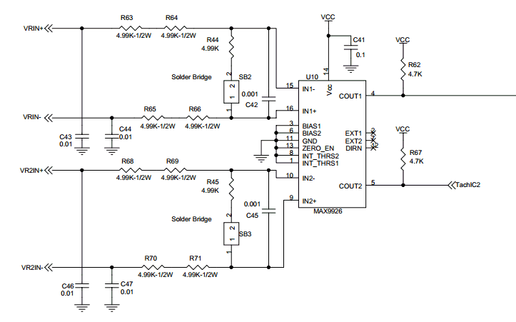
For those who have been wondering (I certainly had been, since I was deemed not good enough to see the schematic for it) I can pretty much guarantee that this is what the TachIn section of the MS3Pro looks like.
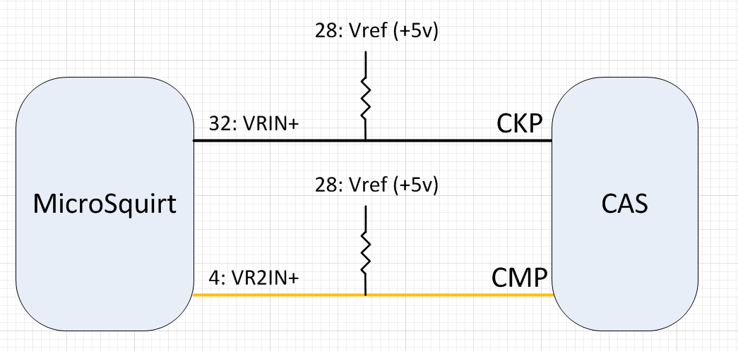
If i were to use a Miata basemap for this, would the CKP or CMP be VR IN#1?
2. Am I able to just split the wire for each outputs to the coil signal pins to set this up on wasted spark?
Last edited by Joe Perez; 10-30-2013 at 08:49 PM.
Reply
1
1
 10-31-2013, 10:01 AM
#13
Elite Member
Thread Starter
iTrader: (8)
Join Date: Dec 2008
Location: Kingston, Ontario
Posts: 2,910
Total Cats: 51
Great. Thanks.
I am planning in these early stages to run the car (1.6) off a Honda Throttle body on a custom inlet manifold. I wont have provisions for an idle valve.
This car is RACE ONLY. Is there going to be a problem with running it without the idle valve?
I am planning in these early stages to run the car (1.6) off a Honda Throttle body on a custom inlet manifold. I wont have provisions for an idle valve.
This car is RACE ONLY. Is there going to be a problem with running it without the idle valve?
Reply
0
0
10-31-2013, 10:09 AM
#15
Elite Member
Thread Starter
iTrader: (8)
Join Date: Dec 2008
Location: Kingston, Ontario
Posts: 2,910
Total Cats: 51
Reading the microsquirt setup guide again... I noticed this...
So I hook the VR1in+ to the crank signal wire from the CAS, VR1in- to the CAS ground and then feed the CAS its required input voltage seperate from the microsquirt harness?
VR return ground (Ampseal pin 33) - there is a separate VR(-) input on the AMPSEAL, this needs to be connected to the VR sensor(s). If you are using two VR sensors, return both back to this wire (these are low current and can be shared on the one wire return path) Do not ground the VR sensor anywhere else, return the ground back to the VR(-) terminal. On the MicroSquirt� EFI controller, this return goes directly back to the VR input circuit's transistor/op amp and not to the ground plane, this keeps the high amplitude VR voltages (and resulting currents) isolated to the VR circuit.
Reply
0
0
10-31-2013, 11:02 AM
#16
mkturbo.com

iTrader: (24)
Join Date: May 2006
Location: Charleston SC
Posts: 15,176
Total Cats: 1,680
As long as the Honda TB has an idle adjust screw to crack it open, I see not problem running without an idle valve. I know Savington does not use them on his race cars.
Last edited by shuiend; 10-31-2013 at 12:09 PM.
Reply
0
0
 10-31-2013, 11:47 AM
#18
Boost Pope
iTrader: (8)
Join Date: Sep 2005
Location: Chicago. (The less-murder part.)
Posts: 33,015
Total Cats: 6,587
Reading the microsquirt setup guide again... I noticed this...
So I hook the VR1in+ to the crank signal wire from the CAS, VR1in- to the CAS ground and then feed the CAS its required input voltage seperate from the microsquirt harness?
VR return ground (Ampseal pin 33) - there is a separate VR(-) input on the AMPSEAL, this needs to be connected to the VR sensor(s). If you are using two VR sensors, return both back to this wire (these are low current and can be shared on the one wire return path) Do not ground the VR sensor anywhere else, return the ground back to the VR(-) terminal. On the MicroSquirt� EFI controller, this return goes directly back to the VR input circuit's transistor/op amp and not to the ground plane, this keeps the high amplitude VR voltages (and resulting currents) isolated to the VR circuit.
That documentation is obsolete (it refers to the OLD circuit), and it ALSO applies only to the use of actual VR sensors, which are inherently differential. You are not using differential VR sensors, so you don't have to worry about keeping the circuits balanced and dealing with high voltage.
You only need two wires between the CAS and the MS- CKP and CMP, as shown in my post above.
Reply
0
0
10-31-2013, 11:51 AM
#19
Elite Member
Thread Starter
iTrader: (8)
Join Date: Dec 2008
Location: Kingston, Ontario
Posts: 2,910
Total Cats: 51
Switched on with part of the main relay- same circuit as the injector power and ecu power.
Im pretty sure this is how you mentioned it, but I am just making sure.
Reply
0
0
10-31-2013, 12:49 PM
#20
Boost Pope
iTrader: (8)
Join Date: Sep 2005
Location: Chicago. (The less-murder part.)
Posts: 33,015
Total Cats: 6,587
Yeah, I assumed that you would just be leaving the existing 12v and GND connections alone- they do not go to the ECU, they're just part of the car's front harness. Assuming you're starting with a complete, stock Miata harness, you don't need to do anything all all with the power and ground wires- they're taken care of already.
Reply
0
0


