MS2 4G63 tach input on v2.2pcb
 12-29-2011, 11:18 PM
#1
Senior Member
Thread Starter
iTrader: (9)

Join Date: Oct 2006
Location: Lexington SC
Posts: 1,176
Total Cats: 35
I am trying to upgrade one of my v2.2 pcb megasquirts to use a Ms2 daughter card, and I am having a hard time getting the Tach inputs to work correctly.
I used this V3.0 PCB diagram as a template:
from:
http://miataturbo.wikidot.com/ms2-a
the board was built/modded (MS1exHrG) using:
http://www.diyautotune.com/tech_arti...azda_miata.htm
The Ms2ex code that I have loaded on the MS2:
http://www.msextra.com/forums/viewto...p?f=91&t=43370
Changes made:
1)MS2 12v input : 12v in on JP1#6 (JS9/CPU pin 16)
2)CMP pin change 11>17: Linked CMP input directly to JP1#5(JS10/CPU pin 17)
added 470ohm pullup from JP1#8 to JP1#5
(no filter cap)
3)CKP : Left 470ohm 12v pullup on unbanded end of D5
4)Swapped SparkA / SparkB
The symptoms:
I am not seeing a stable RPM signal on the Jimstim, It jumps back and forth from a rpm to 1 and never syncs properly. I tested the Jimstim settings with a spare MS that is identical to the MS that I am trying to upgrade to MS2.
I am using the following MS2 tach input settings:
SparkMode: 4G63
TriggerAng: 10 (this can be dailed in once I can get a good rpm read)
Use Cam signal : Yes
Skip pulses: 3
Ignition input capture: Falling edge.
I am confident I can dial in the rest once I can get the tach input circuits working. Your help is much appreciated.

Reply
 0
0

0
 12-30-2011, 08:43 AM
#3
Supporting Vendor


iTrader: (33)
Join Date: Jul 2006
Location: atlanta-ish
Posts: 12,659
Total Cats: 134
Though we usually don't recommend V2.2 for the application, the hardware mods are shown in the manual:
http://www.msextra.com/doc/ms2extra/MS2-Extra_4g63.htm

Reply
0
0
12-30-2011, 08:49 AM
#4
Boost Czar

iTrader: (62)
Join Date: May 2005
Location: Chantilly, VA
Posts: 79,493
Total Cats: 4,080
yeah really you just needed to reverse the polarity of the ckp input:
the cmp can going directly input pin 26 with a 470ohm pullup.
never done it, but that should work.
the cmp can going directly input pin 26 with a 470ohm pullup.
never done it, but that should work.
Reply
0
0
12-30-2011, 06:50 PM
#5
Senior Member
Thread Starter
iTrader: (9)
Join Date: Oct 2006
Location: Lexington SC
Posts: 1,176
Total Cats: 35
Thanks guys, now I have the CKP, and CMP inputs working on the JimStim, syncs up and gives a stable RPM now.
In summary:
To get the Miata 4G63 CKP and CMP (crank and cam) signals working on with a Ms2 daughter card on a v2.2 PCB:
CKP cicuit:

CMP:
Link CMP input directly to JP1#5(JS10/CPU pin 17)
add 470ohm pullup from JP1#8 to JP1#5
Key Settings:
SparkMode: 4G63
Use Cam signal : Yes
Ignition input capture: Falling edge
Now on to the spark outputs, I could not find any dwell numbers on the MS2extra 4G63 docs, are 6 ms Cranking, and 4 ms Maximum Dwell Duration (running) good starting values for 1.6 coil packs?
In summary:
To get the Miata 4G63 CKP and CMP (crank and cam) signals working on with a Ms2 daughter card on a v2.2 PCB:
CKP cicuit:
CMP:
Link CMP input directly to JP1#5(JS10/CPU pin 17)
add 470ohm pullup from JP1#8 to JP1#5
Key Settings:
SparkMode: 4G63
Use Cam signal : Yes
Ignition input capture: Falling edge
Now on to the spark outputs, I could not find any dwell numbers on the MS2extra 4G63 docs, are 6 ms Cranking, and 4 ms Maximum Dwell Duration (running) good starting values for 1.6 coil packs?
Reply
0
0
10-15-2013, 02:52 PM
#6
Junior Member

Join Date: Apr 2013
Location: Va
Posts: 87
Total Cats: -4
Sorry to drag up an old as dirt thread but after 6 days of searching and 2 sets of fryed coil packs I think it's time for me to ask for some guidance
So I have the v2.2 board wired as per above and am using an old zeal daughter board to control the PWM idle valve, although it is set to off in the software.
I can get a nice steady rpm signal on the jimstim, but when I try it on the car I can get the car started for about 30 seconds and then the coils go down. Started with a fresh set of 94 coils then to a 99 set just to keep trying different things I thought would be causing it.
Everything I read says that the spark should be on the falling edge and going high (inverted) when converting to ms2 on the v2.2 board and setting up for the 4g63 input.
I ran out of factory coils laying around so I decided it was a good idea to switch to COP. When I plug in my old mspnp gen 1 the car runs fine on the cop's. when I try the ms2 the ground wire coming off of the coils gets hot in very short order.
Ill upload an msq and some pictures of the harness and board once I get a sec, just kinda hoping someone else has "been there done that"
Reply
0
0
10-16-2013, 07:28 AM
#10
Boost Czar
iTrader: (62)
Join Date: May 2005
Location: Chantilly, VA
Posts: 79,493
Total Cats: 4,080
It clearly says when using the joeP spark output method, which is NOT what you have in your v2.2 board.
yes they do that.
put it back to normal and enjoy not blowing coils cause you set it up wrong.
yes they do that.
put it back to normal and enjoy not blowing coils cause you set it up wrong.
Reply
-1
-1
10-16-2013, 09:29 AM
#11
Junior Member
Join Date: Apr 2013
Location: Va
Posts: 87
Total Cats: -4
Thanks bub
Ill give that a shot and let you know how it works out.
I figure once I get this going ill make a write up for the v2.2 as there aren't many real world examples out there so hopefully someone else will have an easier time with it.
Edit: any suggestions on starting trigger angle or is the 0 degrees that TS defaults to enough timing to get it running you think?
Last edited by Togeneral99; 10-16-2013 at 10:04 AM.
Reply
0
0
10-16-2013, 10:43 AM
#12
Boost Czar
iTrader: (62)
Join Date: May 2005
Location: Chantilly, VA
Posts: 79,493
Total Cats: 4,080
I've made a writeup for a v2.2 here before, but im not sure the pics are still hosted:
https://www.miataturbo.net/megasquir...30/#post673322
you need WAY more trigger angle than that, msI docs suggest a good default value. It's been YEARS since I've touched MSI, but it needs to be well above 0 as a default value.
https://www.miataturbo.net/megasquir...30/#post673322
you need WAY more trigger angle than that, msI docs suggest a good default value. It's been YEARS since I've touched MSI, but it needs to be well above 0 as a default value.
Reply
0
0
10-16-2013, 10:16 PM
#13
Junior Member
Join Date: Apr 2013
Location: Va
Posts: 87
Total Cats: -4
Ok something is clearly not right although we have progress.
I set the coils to normal and set the trigger angle to 10 (played with everything from 0-90) and 10 seemed to line up with the crank pulley. Just for a reference the ms1 wanted a trigger angle of 57 but I feel that is irrelevant.
The problem is that the engine seems to be running on 2 cylinders while the on mspnp runs the car fine so I know the problem is in the ms2 box or wiring.
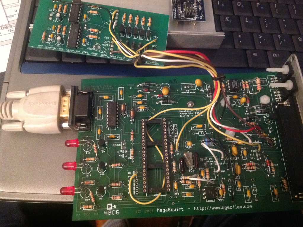
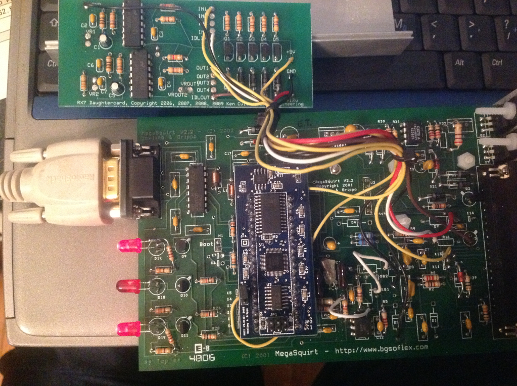
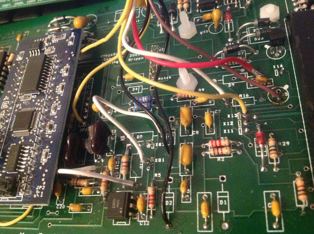
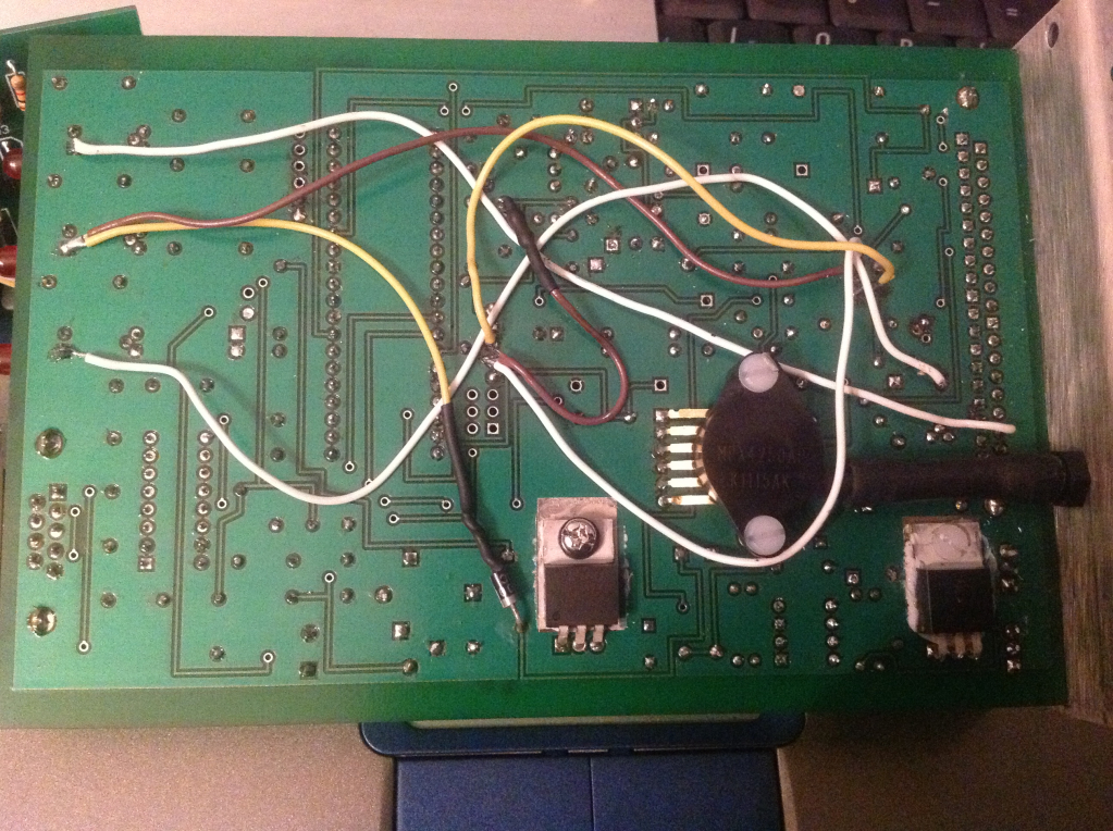
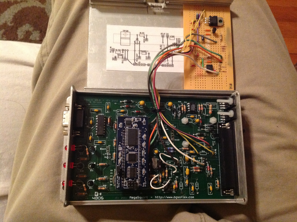
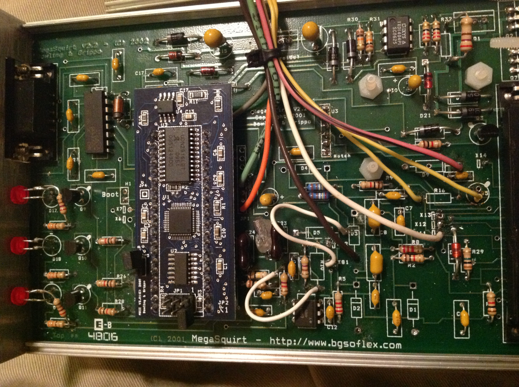
Attached are a couple of pictures of the ms2 setup and its jumpers (I've tried my best to make sure everything matches the v3.0 board all the way down to comparing the schematics of the 2 boards)
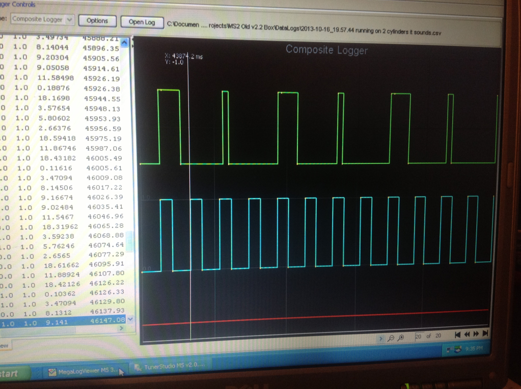
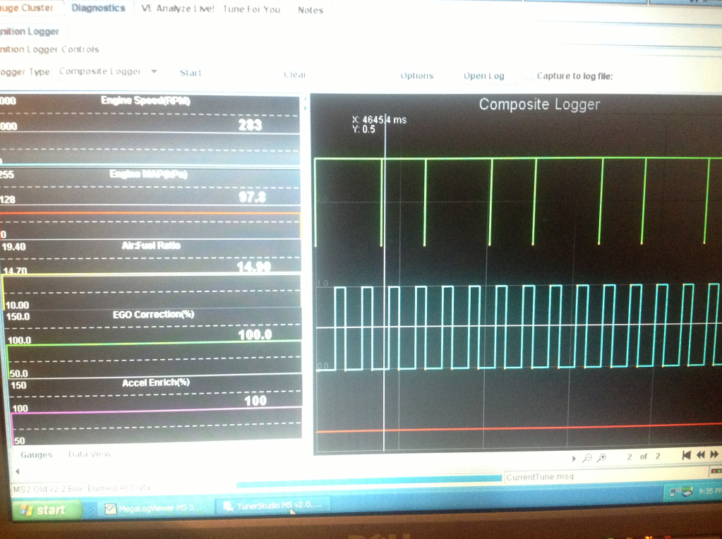
Also I noticed that the composite logs look a bit different on the cam input between the stim and the car
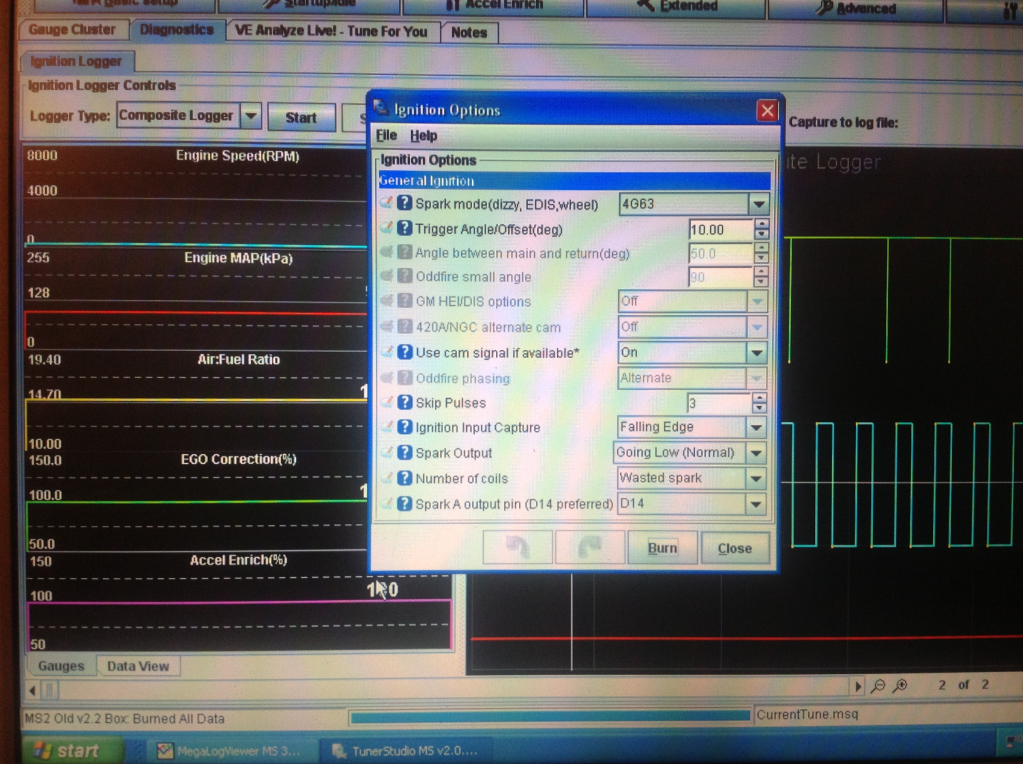
I set the coils to normal and set the trigger angle to 10 (played with everything from 0-90) and 10 seemed to line up with the crank pulley. Just for a reference the ms1 wanted a trigger angle of 57 but I feel that is irrelevant.
The problem is that the engine seems to be running on 2 cylinders while the on mspnp runs the car fine so I know the problem is in the ms2 box or wiring.
Attached are a couple of pictures of the ms2 setup and its jumpers (I've tried my best to make sure everything matches the v3.0 board all the way down to comparing the schematics of the 2 boards)
Also I noticed that the composite logs look a bit different on the cam input between the stim and the car
Reply
0
0
10-16-2013, 10:57 PM
#14
Junior Member
Join Date: Apr 2013
Location: Va
Posts: 87
Total Cats: -4
So in short what I have done to the board is the following:
Added zeal daughter board to provide a tach output and PWM idle control (this could be considered obsolete for this setup as I now have working COP's and a couple of TIP120's I could use instead)
Board needs 12v, 5v & 2 grounds (as per diyautotune's instructions)
12v - banded end of D9
5v - JP1 header pin 8
Gnd - unbanded end of D3
Gnd - unbanded end of D2
Zeal idle mod - per DIY
Remove D9
Remove Q5
Remove R16
Left side of R16 to idle in
Bottom hole of Q5 to idle out
Zeal tach output mod
X4 (pin 36 on the ms2 daughter board, otherwise iac2a or JS2) to "In1" on Zeal DB
"Out1" on Zeal DB to X13, or pin #29 on the DB37
The MS2 DB is supplied 12v by the unmarked hole just to the right and below of X13 as seen on the bottom of the board (yellow wire)
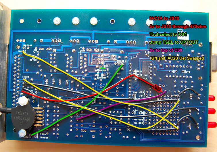
The ckp signal is brought into the board via pin #24 on the db37
D5, D8, R1 & XG1-XG2 jumper are all removed and replaced with:
Jumper from unbanded end of D5 to XG1
Jumper from the bottom of R10 to the top of R11
D8 replaced with a 470 resistor
Cmp signal brought into the board via pin 25 (X11)
Jumper from X11 (underside of board - white wire) to JP1 header pin 5
5V pull-up from JP1 header pin 5 to lower leg of C24 through a 470ohm resistor (although when I put the multimeter on it it measures ~340ohms while attached to the board)
JP1 header pin 5 correlates to pin 17 on the MS2 DB or JS10 according to the schematics
Spark outputs:
Spark output A - wire going from "-" of D17 to X14 (pin 31 on the db37)
Spark output B - wire going from "-" of D19 to pin 36 on the db37
1k resistor from the "-" leg of D17 to the right side of R23 (5v pull-up ?)
1k resistor from the "-" leg or D19 to the right side of R27 (5v pull-up ?)
Fan mod:
Jumper from "-" of D18 to X12 (pin 27 on db37)
1n4001 diode from 12v (unmarked hole just to the left of U5 - if looking from the top) to "-" of D18 as seen on Franks MS2 build page
I think that covers all of the mods done to the board, although this board has gone through a couple of iterations over the years (was on a 7x reluctor signal car hence the zeal DB)
Added zeal daughter board to provide a tach output and PWM idle control (this could be considered obsolete for this setup as I now have working COP's and a couple of TIP120's I could use instead)
Board needs 12v, 5v & 2 grounds (as per diyautotune's instructions)
12v - banded end of D9
5v - JP1 header pin 8
Gnd - unbanded end of D3
Gnd - unbanded end of D2
Zeal idle mod - per DIY
Remove D9
Remove Q5
Remove R16
Left side of R16 to idle in
Bottom hole of Q5 to idle out
Zeal tach output mod
X4 (pin 36 on the ms2 daughter board, otherwise iac2a or JS2) to "In1" on Zeal DB
"Out1" on Zeal DB to X13, or pin #29 on the DB37
The MS2 DB is supplied 12v by the unmarked hole just to the right and below of X13 as seen on the bottom of the board (yellow wire)
The ckp signal is brought into the board via pin #24 on the db37
D5, D8, R1 & XG1-XG2 jumper are all removed and replaced with:
Jumper from unbanded end of D5 to XG1
Jumper from the bottom of R10 to the top of R11
D8 replaced with a 470 resistor
Cmp signal brought into the board via pin 25 (X11)
Jumper from X11 (underside of board - white wire) to JP1 header pin 5
5V pull-up from JP1 header pin 5 to lower leg of C24 through a 470ohm resistor (although when I put the multimeter on it it measures ~340ohms while attached to the board)
JP1 header pin 5 correlates to pin 17 on the MS2 DB or JS10 according to the schematics
Spark outputs:
Spark output A - wire going from "-" of D17 to X14 (pin 31 on the db37)
Spark output B - wire going from "-" of D19 to pin 36 on the db37
1k resistor from the "-" leg of D17 to the right side of R23 (5v pull-up ?)
1k resistor from the "-" leg or D19 to the right side of R27 (5v pull-up ?)
Fan mod:
Jumper from "-" of D18 to X12 (pin 27 on db37)
1n4001 diode from 12v (unmarked hole just to the left of U5 - if looking from the top) to "-" of D18 as seen on Franks MS2 build page
I think that covers all of the mods done to the board, although this board has gone through a couple of iterations over the years (was on a 7x reluctor signal car hence the zeal DB)
Reply
0
0
10-17-2013, 08:44 PM
#15
Junior Member
Join Date: Apr 2013
Location: Va
Posts: 87
Total Cats: -4
Success!
Yesterday when I was able to get the car running it was rough on the MS2 but the MSPNP worked fine so I figured the issue was either in the box or the harness.
Well while the car was running I verified that my CAS signal looked good and I started pulling coils while the engine was running to find the dead cylinder - #3 hmmm well the injectors and the coils are wired in pairs and #2 was firing just fine...so I checked the harness.
Low and behold one of the injector outputs at the 48 pin connector had broke the solder joint loose (don't use Rosen core solder, instead put flux on it and use a small dia solder with silver 2%)
Well I soldered the joint back together and the car purred like a kitten.
So if anyone wants to be a cheap-*** and use a v2.2 board and ms2 daughter board, the above wiring will get you there (I know it was already listed but now it's got pictures and an overly detailed ---- write up!)
The downside to using MS2 and either a v2.2 board or any board for that matter is limited number of outputs. I have:
PWM idle valve - Fidle
Fan control - pin 27
Optional tach output (can use 3 wire coils on a 94 ) - pin 29
Spark output A - pin 31
Spark output B - pin 36
And that's it. Ill probably wire up pin 29 for EBC
Brain thx for the help bub
Yesterday when I was able to get the car running it was rough on the MS2 but the MSPNP worked fine so I figured the issue was either in the box or the harness.
Well while the car was running I verified that my CAS signal looked good and I started pulling coils while the engine was running to find the dead cylinder - #3 hmmm well the injectors and the coils are wired in pairs and #2 was firing just fine...so I checked the harness.
Low and behold one of the injector outputs at the 48 pin connector had broke the solder joint loose (don't use Rosen core solder, instead put flux on it and use a small dia solder with silver 2%)
Well I soldered the joint back together and the car purred like a kitten.
So if anyone wants to be a cheap-*** and use a v2.2 board and ms2 daughter board, the above wiring will get you there (I know it was already listed but now it's got pictures and an overly detailed ---- write up!)
The downside to using MS2 and either a v2.2 board or any board for that matter is limited number of outputs. I have:
PWM idle valve - Fidle
Fan control - pin 27
Optional tach output (can use 3 wire coils on a 94
) - pin 29Spark output A - pin 31
Spark output B - pin 36
And that's it. Ill probably wire up pin 29 for EBC
Brain thx for the help bub
Reply
0
0
05-07-2014, 04:17 PM
#16
Junior Member
Join Date: Apr 2013
Location: Va
Posts: 87
Total Cats: -4
For the sake of posterity, I figured I'd update this with my latest wiring setup.
I removed the zeal board and decided to make my own board for the following reasons:
The zeal board was only being used for idle and took up a good bit of space for the 3-4 components that were actually necessary for the idle mod, and the simple pull-up on the cam signal was inadequate and caused resets every minute or two.
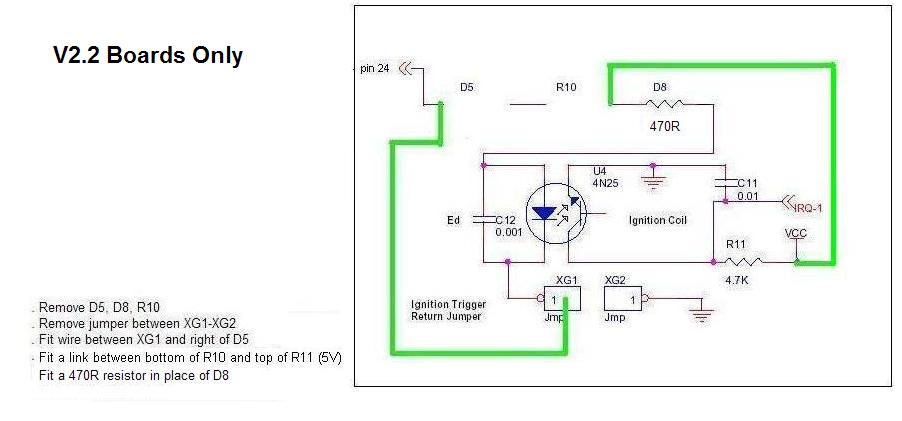
So in making my own board I knew I needed idle and I needed a 4N25 opto isolator for the cam signal ( as can be found here: MS2-Extra Miata 4g63 Manual ), a PWM idle circuit and a switched ground to control my VICS solenoid (BP4W in an NA).
So I made the following board:
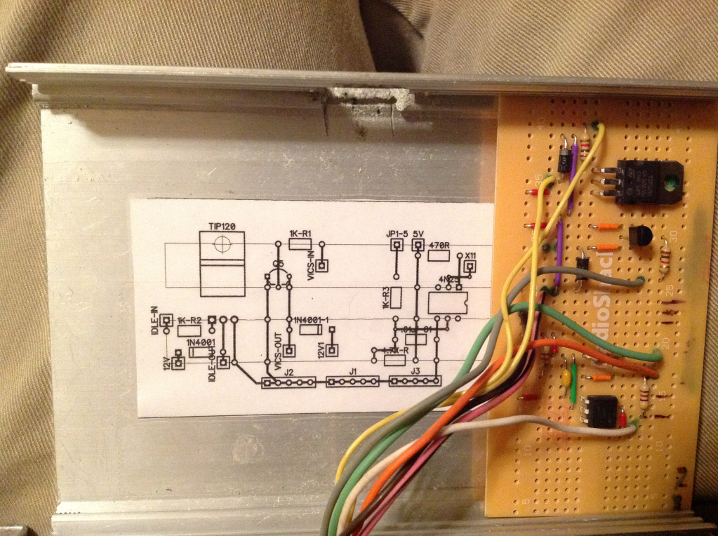
Everything is labeled in the schematic except j1, J2 & J3 - these are the ground plane and connect to the unbanded end of D3 on the 2.2 board.
Idle on my board is wired in exactly the same as the zeal board as shown 2 posts above with the exact same components removed.
Instead of using X4 for my switched ground for the VICS, I used what would be JS11 (JP1 pin 4) and brought it out through X13 (pin 29 on the DB37). (I know the pictures still show it going to X4 though)
I removed the zeal board and decided to make my own board for the following reasons:
The zeal board was only being used for idle and took up a good bit of space for the 3-4 components that were actually necessary for the idle mod, and the simple pull-up on the cam signal was inadequate and caused resets every minute or two.
So in making my own board I knew I needed idle and I needed a 4N25 opto isolator for the cam signal ( as can be found here: MS2-Extra Miata 4g63 Manual ), a PWM idle circuit and a switched ground to control my VICS solenoid (BP4W in an NA).
So I made the following board:
Everything is labeled in the schematic except j1, J2 & J3 - these are the ground plane and connect to the unbanded end of D3 on the 2.2 board.
Idle on my board is wired in exactly the same as the zeal board as shown 2 posts above with the exact same components removed.
Instead of using X4 for my switched ground for the VICS, I used what would be JS11 (JP1 pin 4) and brought it out through X13 (pin 29 on the DB37). (I know the pictures still show it going to X4 though)
Reply
0
0

Thread
Thread Starter
Forum
Replies
Last Post
Zaphod
MEGAsquirt
47
10-26-2018 11:00 PM
StratoBlue1109
Miata parts for sale/trade
21
09-30-2018 01:09 PM


