Setting up an MS3Pro
 07-19-2013, 11:48 PM
#1
Elite Member

Thread Starter
iTrader: (3)
Join Date: Aug 2006
Location: San Diego, CA
Posts: 3,047
Total Cats: 12
So, um, I spent all this time wiring up everything, and um... I'm finding there's all these little shady secrets which don't make it into the documentation, just like what got me to hate MSII before it.
If you run your VVT on "high current out" which you'd want to give some serious thought to since it's like 7 ohms or something, you can't use a different frequency than the PWM Idle valve. Which is a bit of a shame, since... you know, idle valve likes to see 500 Hz (per Jerrah, here), and the VVT [edit: originally VICS] solenoid wants to see 285 HZ per this complicated path to get to Reverant's measurement.
And let's not forget that I've got an old FM (TWO old FM) boost solenoid(s), neither of which FM knows anything about, and they said something to the effect of "we never could get those to work right" when I asked what the Uberdollar system runs them at.
Fine. This isn't a **** on FM post, it's a **** on MS post.
So, does anyone know how I can get three different high current outputs from the MS at different, higher-than-100Hz PWM's from an MS3-Pro?
My guess is no. Of course, I was going to compromise and make everything 380 hz (already made the idle much louder than it used to be). I guess some of that comes down to the guts of the MS3Pro, which I don't know that well. The guys there support the product pretty well but this information seems of general interest so I thought I'd try to get a thread started. Perhaps I'll do a write up of "how to actually use the MS3Pro on a miata the way they say you can on the telly". The capability is there but the documentation leaves you asking a lot more questions when you're actually installing than you thought you would.
P.S. Anyone know how to get the ignition outputs to work for things like CEL and other warning lights? I thought I'd be all over this but it turns out not to be going well.
Last edited by AbeFM; 07-22-2013 at 12:28 PM.

Reply
 0
0

0
07-21-2013, 09:24 PM
#2
Junior Member

Join Date: Aug 2009
Location: Lake Jackson, TX
Posts: 166
Total Cats: 7
Subscribed.
I'm going to be interested in this thread. I've got an MS3-Pro in hand, but haven't had time to alter the car for it or prep the unit itself for the car. I probably won't be able to contribute as much as more experienced users, but I will contribute what I can once I finally get it on the car.
I'm going to be interested in this thread. I've got an MS3-Pro in hand, but haven't had time to alter the car for it or prep the unit itself for the car. I probably won't be able to contribute as much as more experienced users, but I will contribute what I can once I finally get it on the car.
Reply
0
0
07-22-2013, 07:45 AM
#3
Boost Czar

iTrader: (62)
Join Date: May 2005
Location: Chantilly, VA
Posts: 79,493
Total Cats: 4,080
If you run your VVT on "high current out" which you'd want to give some serious thought to since it's like 7 ohms or something, you can't use a different frequency than the PWM Idle valve. Which is a bit of a shame, since... you know, idle valve likes to see 500 Hz (per Jerrah, here), and the VICS solenoid wants to see 285 HZ per this complicated path to get to Reverant's measurement.
...
So, does anyone know how I can get three different high current outputs from the MS at different, higher-than-100Hz PWM's from an MS3-Pro?
...
So, does anyone know how I can get three different high current outputs from the MS at different, higher-than-100Hz PWM's from an MS3-Pro?
There's also been two groupings of High-Freq. PWM outputs.
On the MS3X it's:
Code:
Group A			Group B
PP0 – Inj 1		PP2 – Idle
PP1 – Inj 2		PP3 – Boost
PP4 – Nitrous 1		PP6 – VVT
PP5 – Nitrous 2		PP7 – FIDLE (mainboard)
There's no reason you need PWM with VICS. Put it on a spare programmable on/off INJ output. Now you can make the idle valve whatever you need and the VVT whatever you need and you can start another long ranting post about something else easily solvable.
P.S. Anyone know how to get the ignition outputs to work for things like CEL and other warning lights? I thought I'd be all over this but it turns out not to be going well.
Last edited by Braineack; 07-22-2013 at 10:25 AM.
Reply
0
0
07-22-2013, 10:11 AM
#4
2 Props,3 Dildos,& 1 Cat

iTrader: (8)
Join Date: Jun 2005
Location: Fake Virginia
Posts: 19,338
Total Cats: 573
what brain sez. I dont know if the MS3Pro does "pwm by groups" but the X does. I put VVT on Nitrous 1 or 2 and idle on idle and ran them at different hz.
Also why does VICS need a PWM if it's just open or closed?
FWIW vvt works fine at the idle frequency (380?)
Also why does VICS need a PWM if it's just open or closed?
FWIW vvt works fine at the idle frequency (380?)
Reply
0
0
07-22-2013, 12:27 PM
#5
Elite Member
Thread Starter
iTrader: (3)
Join Date: Aug 2006
Location: San Diego, CA
Posts: 3,047
Total Cats: 12
Ha. I noticed that this morning - I meant VVT, I'm just a looser(sic).
VVT is supposed to be 500, which is quite a bit higher than the 285 VVT should work at.
VVT is supposed to be 500, which is quite a bit higher than the 285 VVT should work at.
Reply
0
0
07-22-2013, 12:31 PM
#6
Elite Member
Thread Starter
iTrader: (3)
Join Date: Aug 2006
Location: San Diego, CA
Posts: 3,047
Total Cats: 12
...and no, they don't really set up groups for the PWMs. I have a feeling they exist, but it's not at all clear in the documentation or even in talking to the guys. I'll recommend they format it as such since we've been discussing edits to the manual.
Reply
0
0
07-22-2013, 01:52 PM
#8
Supporting Vendor

Join Date: Sep 2006
Posts: 2,332
Total Cats: 67
I believe the groups are INJ I / INJ J / High Current outputs on one bank and the PWM outputs on the other. However, I'll need to check with James to confirm that. I'll let you know what I find.
Most boost solenoids are low frequency, FWIW. Never seen a high frequency one.
Most boost solenoids are low frequency, FWIW. Never seen a high frequency one.
Reply
0
0
07-22-2013, 03:19 PM
#9
Senior Member
iTrader: (1)

Join Date: Sep 2011
Location: Lambertville, NJ
Posts: 1,215
Total Cats: 74
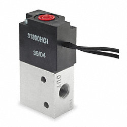
I'm running an ancient FM boost control solenoid. I believe it was purchased in 2000. It's just a sheet-metal cylinder with plastic bits at the end and three ports. Two electric connectors complete the picture (from memory they may be white and red).
Looks similar to this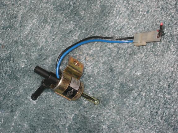
It's running rather well at 26Hz with a 30ms control interval.
Looks similar to this
It's running rather well at 26Hz with a 30ms control interval.
Reply
0
0
 07-23-2013, 09:57 AM
#12
2 Props,3 Dildos,& 1 Cat
iTrader: (8)
Join Date: Jun 2005
Location: Fake Virginia
Posts: 19,338
Total Cats: 573
Matt, those don't sound like the same "groups" we're talking about with the MS3X board.
There are certain outputs that share a high frequency PWM. This doesn't necessarily include the injector outputs because they're a different layout/circuit.
It also only applies to the higher frequencies, not the double digit ones for things like boost control.
There are certain outputs that share a high frequency PWM. This doesn't necessarily include the injector outputs because they're a different layout/circuit.
It also only applies to the higher frequencies, not the double digit ones for things like boost control.
Reply
0
0
07-23-2013, 10:10 AM
#14
Boost Czar
iTrader: (62)
Join Date: May 2005
Location: Chantilly, VA
Posts: 79,493
Total Cats: 4,080
It would be grouped:
INJ I
INJ J
High Current Out 1
High Current Out 2
High Current Out 3
and
PWM (idle) out 1
PWM out 2
PWM out 3
So put Idle on PWM 1 and VVT on High Current 1 and call it a day.
INJ I
INJ J
High Current Out 1
High Current Out 2
High Current Out 3
and
PWM (idle) out 1
PWM out 2
PWM out 3
So put Idle on PWM 1 and VVT on High Current 1 and call it a day.
Reply
0
0
07-23-2013, 08:08 PM
#15
Elite Member
Thread Starter
iTrader: (3)
Join Date: Aug 2006
Location: San Diego, CA
Posts: 3,047
Total Cats: 12
Yes, the valve(s) are the two shown.
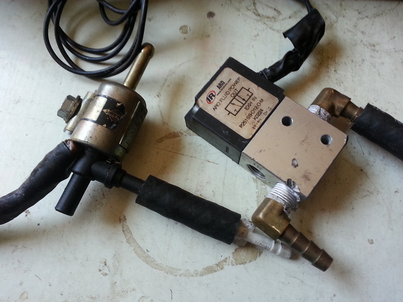
I was running the bigger one Brain posted. I don't really know which is better. I guess I'll cut things down further.
I seem to recall there being a pin I could use for both low and mid freq, guess I'll have to dig for it.
Bang! Explain that smartypants. That's plural, not pants plural, but people.
I was running the bigger one Brain posted. I don't really know which is better. I guess I'll cut things down further.
I seem to recall there being a pin I could use for both low and mid freq, guess I'll have to dig for it.
Bang! Explain that smartypants. That's plural, not pants plural, but people.
Reply
0
0
07-24-2013, 07:34 AM
#16
Boost Czar
iTrader: (62)
Join Date: May 2005
Location: Chantilly, VA
Posts: 79,493
Total Cats: 4,080
the ARO valve is better. It's the same unit that DIY current sells as a boost controller.
Not quite sure I understand what you are saying.
if you look at the mid/high selections, that represents all the pins of the two banks I posted in #14; those same being all listed in the slow selections as well.
So go turn Idle Out to HCO1 and say 1000Hz, go back to boost and try to set HCO2 to 511Hz and see it complain.
I seem to recall there being a pin I could use for both low and mid freq, guess I'll have to dig for it.
if you look at the mid/high selections, that represents all the pins of the two banks I posted in #14; those same being all listed in the slow selections as well.
So go turn Idle Out to HCO1 and say 1000Hz, go back to boost and try to set HCO2 to 511Hz and see it complain.
Reply
0
0
07-24-2013, 12:25 PM
#17
Elite Member
Thread Starter
iTrader: (3)
Join Date: Aug 2006
Location: San Diego, CA
Posts: 3,047
Total Cats: 12
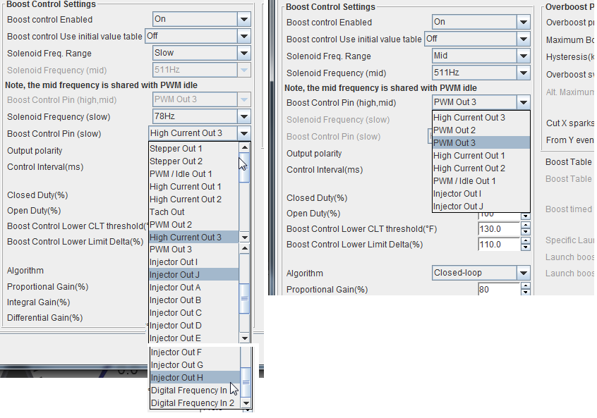
What freq is good for the ARO valve then? Is there a better control interval to use with it?
I've got:
EBC - Slow, PWM Out 3, 39 Hz
P/I/D: 80/10/3 which is based on nothing but 80/20/1 being oscilatey. But I was bouncing off overboost (set to a conservative 160 kpa - or 8psi)
Anyway,
EBC - Slow, PWM Out 3, 39 Hz
VVT - PWM Out 2, 511 Hz
IDLE -PWM/Idle Out 1, 511 Hz
Idle and VVT are both tied to "mid", and EBC can use mid or slow. When using Mid you get the choices shown above, and when using Slow you get the (other) choices, shown above. Meaning they aren't tied to specific pins, the limitation is timers in the CPU, not the pins on it.
At least, that's my interpretation since I'm using an output that's listed on both lists and it is working fine.
Reply
0
0
07-24-2013, 12:29 PM
#19
Boost Czar
iTrader: (62)
Join Date: May 2005
Location: Chantilly, VA
Posts: 79,493
Total Cats: 4,080
you have a conflict error when that happens (ie, you put two things one the same function).
under basic settings there's an option to view all i/os.
for the ARO valve, use 39Hz. PID will end up around 20-20-100
I don't see how you are overboosting with 80 P. you have the polarity inverted right? the closed duty and open duty refer to the wastegate not the solenoid.
under basic settings there's an option to view all i/os.
for the ARO valve, use 39Hz. PID will end up around 20-20-100
I don't see how you are overboosting with 80 P. you have the polarity inverted right? the closed duty and open duty refer to the wastegate not the solenoid.
Reply
0
0
07-25-2013, 04:14 AM
#20
Elite Member
iTrader: (1)

Join Date: Jun 2006
Location: Warrington/Birmingham
Posts: 2,642
Total Cats: 42
Depending on what code version you have. With the latest release and beta's that has been flipped so it actually makes sense i.e. more duty = more boost rather than the other way around.
Reply
0
0


