Wheel of Timing. Success at last!
 05-08-2008, 03:18 PM
#41
Junior Member

Join Date: Feb 2007
Location: 11368 miles from where i would like to be
Posts: 269
Total Cats: 92
Someone probably mentioned this, or you already know, but if your wave form post conditioning has two equal sized gaps around missing tooth (one negative, one positive) then the vr sensor wire itself is backwards and inverting the output of the conditioner will not help. You should get one long gap from it because it only recognises the shallower slope in one direction. You want it to not be recognised.
EDIT : This ^ is all wrong :-)
Fred.
EDIT : This ^ is all wrong :-)
Fred.
Last edited by rb26dett; 05-08-2008 at 05:41 PM. Reason: Ha ha, just in the nick of time :-)

Reply
 0
0

0
05-08-2008, 05:18 PM
#42
Boost Pope


Thread Starter
iTrader: (8)
Join Date: Sep 2005
Location: Chicago. (The less-murder part.)
Posts: 33,019
Total Cats: 6,587
Someone probably mentioned this, or you already know, but if your wave form post conditioning has two equal sized gaps around missing tooth (one negative, one positive) then the vr sensor wire itself is backwards and inverting the output of the conditioner will not help. You should get one long gap from it because it only recognises the shallower slope in one direction. You want it to not be recognised.
Early on, I experimented with both polarities of the VR sensor. The one I am using now is the one which I interpreted to have been commonly judged to be "correct" by the MSExtra crowd. The only difference between the two is the two is the polarity of the output. In the following, the upper trace is the output of the VR sensor as wired presently on my car, the lower trace is the output of the VR sensor if I were to reverse it:

Now, both the "Standard" R3.0 conditioner and the LM1815-based circuit act as zero-crossing detectors. In other words, any time the input signal crosses from negative to positive, or from positive to negative, the output of the conditioner will transition from one state to another.
So, assuming that both of the two sensors above were plugged into the same conditioner, the output would be as indicated by the yellow traces below. The upper signal is "correct", the lower signal is "incorrect". Don't argue with me on this yet, I'll explain my reasoning further down:

The key point here is that the output signal changes at each zero-crossing of the input signal, and the input signal is always going to zero-cross appx. halfway through a cycle.
Changing the polarity of the decoder (inverted vs. non-inverted) does not change this fact, it merely flips the output signal relative to the input signal. Here are the same two input waveforms (top = mine, bottom = reversed) plugged into a VR decoder whose output is inverting relative to its input:

Now, permit me to blow your mind. In the above image, the output trace on the bottom is correct, and the one on the top is wrong. The input (green traces) haven't changed from one picture to the next, the only difference here is that we inverted the output on this one.
Ok, I will now explain my reasoning. The way MS "sees" this signal is by looking at the falling edges of the signal which is presented to the IRQ pin of the CPU. Turn to page 115 of the MC68HC908GP32 datasheet, and you will see:
The external interrupt pin is falling-edge-triggered
Falling edge triggered. The MS cannot "see" the rising edges of the input signal, it can only count the time elapsed between concurrent falling edges. So, let's zoom in on that signal a bit. As before, upper trace is exactly as wired on my car, lower trace is your suggestion- reverse VR polarity but leave decoder polarity alone:

Now, I've measured the time between falling edge in red. Since this is a bitmap image, they're listed in pixels rather than milliseconds or degrees, because it's easier. In the upper trace, each "normal" cycle (from one falling edge to the next) lasts appx. 90 pixels. The missing tooth cycle however, is roughly double this, or 181 pixels from the falling edge of the "last" tooth, across the gap, to the falling edge of the "first" tooth.
In the lower trace, each "normal" cycle is still about 90 pix, but look what happens in the gap- instead of one huge 180 pixel gap, you have two smaller gaps- the first consisting of the whole low half of the last tooth and roughly the first half of the gap, and the second consisting of the second half of the gap plus the whole high period of the first tooth. The MS isn't going to know what to do with that- it's expecting a bunch of nice, consistent falling edges each evenly spaced, followed by one big gap appx 2x the normal duration between falling edges, and then back to the regular spacing until the next full rotation.
So I honestly don't understand your concept of "one big gap" apart from to say that this is exactly what I have built, drawn, and described. One big gap between sequential falling edges of the output.
If you still disagree, then please either show me a scope capture or draw me a picture, because I clearly don't understand what you're trying to describe.
Reply
0
0
05-08-2008, 05:40 PM
#43
Junior Member
Join Date: Feb 2007
Location: 11368 miles from where i would like to be
Posts: 269
Total Cats: 92
You are 100% right and I'm 200% wrong :-)
<reaches for edit button>
I'd better say something intelligent before the shred of credibility I had fades :
It has to be those falling edges because of the hysteresis on the rising edge of the input signal and the variable height of the waves with speed that cause the timing of the leading edge of the square wave to vary with rpm.
My apologies.

Excuses : One glass of wine, many early mornings, too many lines of code :-) (weak, I know)
<reaches for edit button>
I'd better say something intelligent before the shred of credibility I had fades :
It has to be those falling edges because of the hysteresis on the rising edge of the input signal and the variable height of the waves with speed that cause the timing of the leading edge of the square wave to vary with rpm.
My apologies.
Excuses : One glass of wine, many early mornings, too many lines of code :-) (weak, I know)
Reply
0
0
05-08-2008, 05:58 PM
#44
Boost Pope
Thread Starter
iTrader: (8)
Join Date: Sep 2005
Location: Chicago. (The less-murder part.)
Posts: 33,019
Total Cats: 6,587
Don't be too hard on yourself- this was a good thought exercise for me. Up 'till now I hadn't really sat down and plotted all the variables, and in fact I myself misjudged this setup earlier in the week, which on Tuesday left me stranded in a parking lot and cost me a $77 tow charge and a vacation day at work.
Because the output of the sensor is symmetrical, I've come to the conclusion that there is not an absolute "right" and "wrong" polarity for the sensor itself. Rather, there is a right and wrong only when it comes to the relationship between the input to the decoder and the output of the decoder insofar as the output polarity relative to the input polarity is concerned. In fact, the way my sensor is wired would be technically "wrong" for the LM1815-based decoder, simply because it is an inverting circuit.
For what it's worth, this is the image that sent me down the wrong path:

It shows the input polarity the same as mine (slope is upgoing during the missing tooth) however it incorrectly implies that rising edge of the input signal is the trigger point. The reason is that this image is from the MS-2 documentation. On the MS-1, the primary trigger goes straight into the hardware interrupt pin of the 68HC908 microprocessor, which is an active-low input. On the MS-2, this input goes to a GPIO pin of the MC9S12C64 (IOC0) which I believe is configured as a timer control (reading C makes my eyes water...) and that input does indeed appear to be active-high.
Because the output of the sensor is symmetrical, I've come to the conclusion that there is not an absolute "right" and "wrong" polarity for the sensor itself. Rather, there is a right and wrong only when it comes to the relationship between the input to the decoder and the output of the decoder insofar as the output polarity relative to the input polarity is concerned. In fact, the way my sensor is wired would be technically "wrong" for the LM1815-based decoder, simply because it is an inverting circuit.
For what it's worth, this is the image that sent me down the wrong path:
It shows the input polarity the same as mine (slope is upgoing during the missing tooth) however it incorrectly implies that rising edge of the input signal is the trigger point. The reason is that this image is from the MS-2 documentation. On the MS-1, the primary trigger goes straight into the hardware interrupt pin of the 68HC908 microprocessor, which is an active-low input. On the MS-2, this input goes to a GPIO pin of the MC9S12C64 (IOC0) which I believe is configured as a timer control (reading C makes my eyes water...) and that input does indeed appear to be active-high.
Reply
0
0
05-08-2008, 06:09 PM
#45
Junior Member
Join Date: Feb 2007
Location: 11368 miles from where i would like to be
Posts: 269
Total Cats: 92
I'm telling you, something about this site brings out the worst in me :-)
Just be aware of that hysteresis delay (on the left) that varies with rpm!
Sorry to have spammed your thread!
Fred.
Just be aware of that hysteresis delay (on the left) that varies with rpm!
Sorry to have spammed your thread!
Fred.
Reply
0
0
05-08-2008, 06:30 PM
#46
Boost Pope
Thread Starter
iTrader: (8)
Join Date: Sep 2005
Location: Chicago. (The less-murder part.)
Posts: 33,019
Total Cats: 6,587
Yup. I learned a while back (while waging war against my CAS) that this is what the "Hardware Latency (us)" value under Advanced Code Options is for. In my setup, the latency seems to be in the neighborhood of ~150us. With that value plugged in, and the ignition locked at 10�BTDC, I can rev the engine from idle to redline while observing the pulley with a timing gun and the timing remains stable. Lower values cause the timing to self-retard as RPM increases.
Reply
0
0
05-09-2008, 10:50 AM
#47
Junior Member
Join Date: Feb 2007
Location: 11368 miles from where i would like to be
Posts: 269
Total Cats: 92
Hmm, I think that is for latency in the code/cpu hardware, but again (quite probably lol) I could be wrong. The delay I'm talking about varies with RPM such that a fixed offset like that would not work correctly. It varies because the amplitude of the sine wave from the raw sensor varies too, and consequently the rise time is much shorter at high revs and longer at low revs (eg cranking). Do you see what I mean? The ignition in MS2 is bit banged from timer interrupted code that has a latency before running after the timer "goes off". Because of that delay you need to set that figure (I think) :-)
Fred.
Fred.
Reply
0
0
05-09-2008, 11:17 AM
#48
Boost Pope
Thread Starter
iTrader: (8)
Join Date: Sep 2005
Location: Chicago. (The less-murder part.)
Posts: 33,019
Total Cats: 6,587
I found by experimentation that the "Hardware Latency" setting, in MS1 at least, compensates for fixed thruput latency in the trigger circuit. For example, when I was having mis-trigger problems with my CAS, I kept building circuits with larger and larger caps on them, causing the latency to increase, which manifested itself by the timing tending to retard as RPM increased. By locking timing at 10� and observing the difference in actual timing between 1,000 RPM and 6,000 RPM (say, 5� as an example). That's 1� per thousand, a latency of 166 microseconds. Entering this number corrected the drift.
With the new (VR) circuit, I can say only that variable latency on the rising edge of the signal is inconsequential, and that by performing a similar test I have observed my timing to be constant across the RPM range with a correction of ~140us.
With the new (VR) circuit, I can say only that variable latency on the rising edge of the signal is inconsequential, and that by performing a similar test I have observed my timing to be constant across the RPM range with a correction of ~140us.
Reply
0
0
05-09-2008, 01:32 PM
#49
Supporting Vendor

Join Date: Sep 2006
Posts: 2,332
Total Cats: 67
The latency is there to compensate for physical hardware issues. James put that in the code at the 2007 MegaMeet when we had trouble with an engine that was having high RPM timing retard issues. It turned out that the VR sensor itself had a small delay in it. So the latency is there to compensate for "lag times" with real world sensors and real world input conditioners.
Reply
0
0
05-10-2008, 01:19 PM
#50
Junior Member
Join Date: Feb 2007
Location: 11368 miles from where i would like to be
Posts: 269
Total Cats: 92
OK, sure, but the interrupt latency does exist, and you will be correcting for both unless J&K have already corrected for the ISR latency in code (probably they have).
The electrical hardware can have a propagation delay in it, true, but I'm not certain the sensor (which is simply a coil and magnet) can have one unless there is capacitance present as Joe says.
Still, the hysteresis caused delay is not constant with RPM, so you can't use that edge for triggering regardless of all else.
If you read the data sheet it turns on once the voltage reaches hysteresis and off again exactly at the zero crossing after being "armed". Because the rise rate changes with RPM so does the time delay caused by this and you won't get a consistent signal from it if you try to use that edge.
Fred.
Reply
0
0
05-10-2008, 04:40 PM
#51
Boost Pope
Thread Starter
iTrader: (8)
Join Date: Sep 2005
Location: Chicago. (The less-murder part.)
Posts: 33,019
Total Cats: 6,587
Oh, you're talking about the LM1815. I get it now.
I wound up not using that, because it was missing teeth occasionally. Instead I copied the VR circuit from the 3.0 schematic. It seems to put out a consistent signal on both rising and falling edges. It's not trying to do some fancy adaptive zero-crossing detection, you just set a pot to control the switchpoint (by adjusting the bias voltage on the + input of the first opamp) and set another pot to adjust the hysteresis (by adjusting the feedback).
I wound up not using that, because it was missing teeth occasionally. Instead I copied the VR circuit from the 3.0 schematic. It seems to put out a consistent signal on both rising and falling edges. It's not trying to do some fancy adaptive zero-crossing detection, you just set a pot to control the switchpoint (by adjusting the bias voltage on the + input of the first opamp) and set another pot to adjust the hysteresis (by adjusting the feedback).
Reply
0
0
10-14-2011, 11:32 AM
#54
Elite Member

Join Date: Jul 2005
Posts: 6,420
Total Cats: 84
If you change the gap the "wrong" edges can move relative to the actual crank position, but the "right" edges will stay. Also, if there is a bit of runout in the wheel, the correct edges will be more evenly spaced while the wrong edges move around a bit.
In the above diagram, *if* the ECU needed rising edges from the VR processing circuit, the polarity is correct.
The reason for this is the precise zero crossing on a VR sensor is when the "center of mass" of a tooth just passes the sensor - the tooth goes from "moving towards' to "moving away." This point is very distinct, especially if the teeth are smaller then the gaps. The opposite polarity zero-crossing point, where the sensor is over a gap, and the 2 nearby teeth are equidistant from the sensor, is arguably less distinct. This is because the flux density when teeth are away from the sensor, is weakest. And also, because the flux lines are split between the 2 nearby teeth, and have to go through a longer distance to make its way back.
For this reason too, you want the missing tooth to be in a non-critical part of the engine cycle, e.g. just after a TDC event, where a slight error in the timing of the first tooth after the missing tooth, doesn't affect ignition timing.
Funny how I googled this topic and got here.
Reply
0
0
10-18-2011, 07:57 AM
#56
Junior Member
Join Date: Feb 2007
Location: 11368 miles from where i would like to be
Posts: 269
Total Cats: 92
BTW, there are other reasons for not using the other edge too:
1) It's in a different place at different engine speeds
2) If the teeth are narrow and the gaps wide (which is valid) then they're not even close to correct.
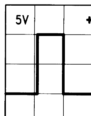
Take toyota for an example:
Note that the teeth are approximately half the size of the gaps on the outer ring.
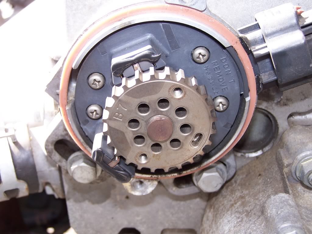
But worse, that the inner only has a small tooth, and 360 of almost nothing.
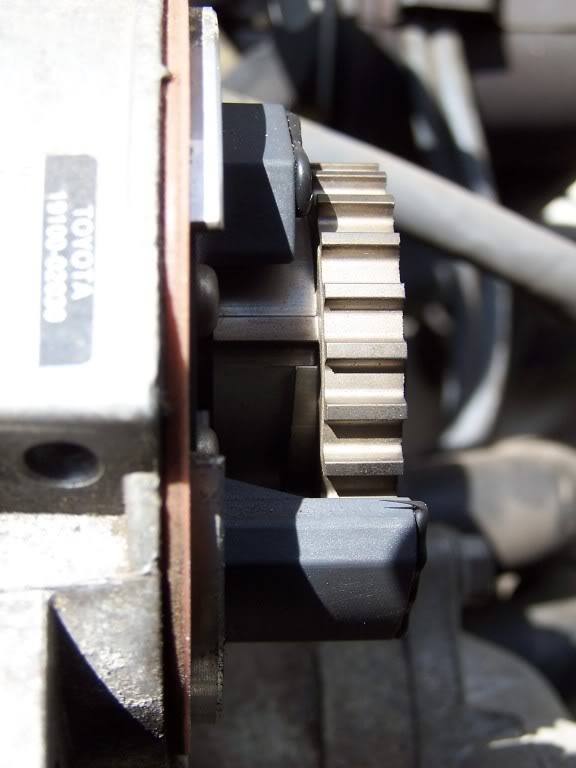
Note, they use a ramp on the non tooth section to make sure the magnetic flux is slightly negative before it goes very positive again, to ensure that edge is where it should be in the processed signal.
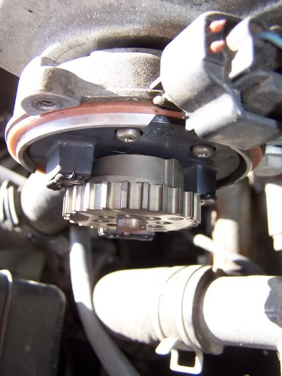
Fred.
1) It's in a different place at different engine speeds
2) If the teeth are narrow and the gaps wide (which is valid) then they're not even close to correct.
Take toyota for an example:
Note that the teeth are approximately half the size of the gaps on the outer ring.
But worse, that the inner only has a small tooth, and 360 of almost nothing.
Note, they use a ramp on the non tooth section to make sure the magnetic flux is slightly negative before it goes very positive again, to ensure that edge is where it should be in the processed signal.
Fred.
Reply
1
1
10-18-2011, 09:30 AM
#58
Elite Member
iTrader: (1)

Join Date: Jun 2006
Location: Warrington/Birmingham
Posts: 2,642
Total Cats: 42
Missing tooth is for TDC, CMP is for phase (crank does 720deg for each cam's 360deg). You need to know the phase to know which one out of 1 and 4, (or 2&3), are supposed to be firing.
Reply
0
0


