Upgraded to MS3X. Losing sync on cranking
 03-15-2012, 01:04 PM
#1
Elite Member
Thread Starter
iTrader: (24)

Join Date: Jul 2007
Location: Cypress, TX
Posts: 3,759
Total Cats: 35
Got everything completed. I didn't switch the spark outputs out of laziness and just went ahead and wired fuel and spark through the ms3x. My board now looks like a normal MS2 build, except for IAC1A and IGN wires. I'm still running on the CAS with the cam input going to the MS3X. Pullup jumper for the cam input is installed, and the pots are set fully counter-clockwise, with R11 2 turns clockwise from that point.
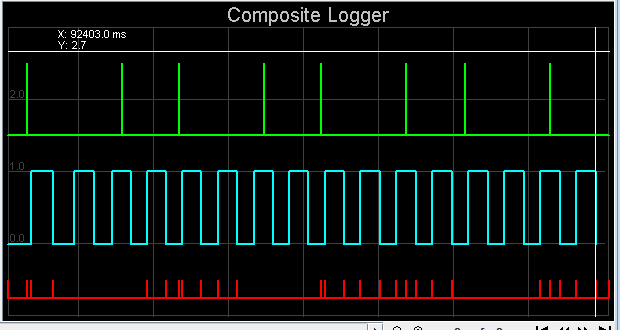
I'm losing sync when cranking. Running a map posted by Brain last year to check my settings against. Here's a composite log that doesn't look quite right. Any ideas?
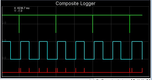
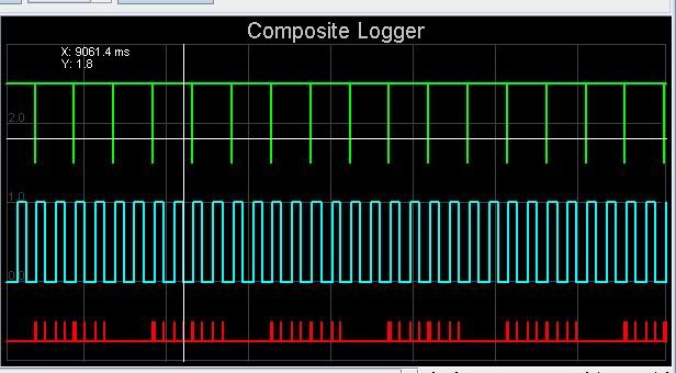
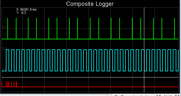
And the same log, zoomed out so you can see the sync error pattern.
I'm losing sync when cranking. Running a map posted by Brain last year to check my settings against. Here's a composite log that doesn't look quite right. Any ideas?
And the same log, zoomed out so you can see the sync error pattern.

Reply
 0
0

0
03-15-2012, 01:15 PM
#2
Boost Czar


iTrader: (62)
Join Date: May 2005
Location: Chantilly, VA
Posts: 79,493
Total Cats: 4,080
your crank and cam are not on the same polarity.
what input method are you using for each?
It sounds like you still have crank going through the opto circuit like a typical MSII build and the Cam input into the MS3X. Is that correct?
if so, you'll need to mod it slightly.
what input method are you using for each?
It sounds like you still have crank going through the opto circuit like a typical MSII build and the Cam input into the MS3X. Is that correct?
if so, you'll need to mod it slightly.
Reply
0
0
03-15-2012, 01:21 PM
#3
Elite Member
Thread Starter
iTrader: (24)
Join Date: Jul 2007
Location: Cypress, TX
Posts: 3,759
Total Cats: 35
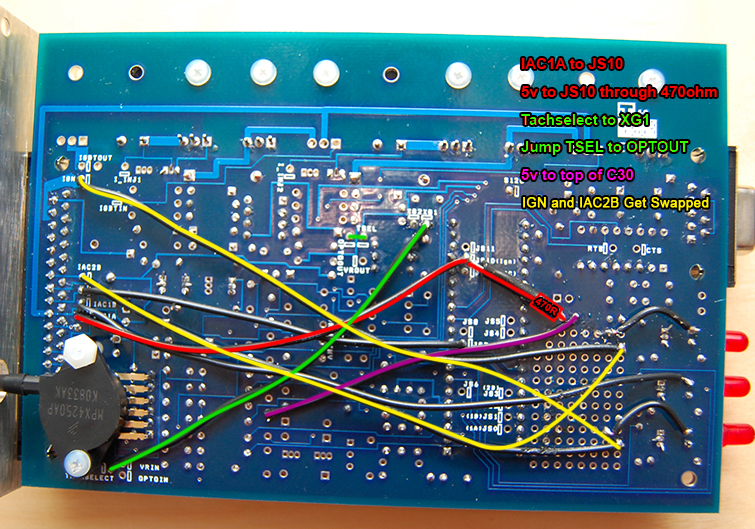
Alright then. To fix this, I need to remove the green wire and jumper. Then jump put jumpers in D1 and D2, between XG1 and XG2, and jump Tachselect to optoin, correct?
Reply
0
0
03-15-2012, 01:32 PM
#4
Boost Czar
iTrader: (62)
Join Date: May 2005
Location: Chantilly, VA
Posts: 79,493
Total Cats: 4,080
okay. so:
Remove the green jumper from Tachselect to XG1
Remove the two red wires (should already be gone-thats the cam input)
remove the Purple jumper
Jump D1
Jump D2.
Jump XG2 and XG1
Jump Tachselect to Optoin
Add a pull-up like the yellow line shown in the image below:
that should fix it. make sure your set to falling edge trigger capture. This will use the same input method (opto circuit) but reverese to polarity to match that of the cam signal.
Reply
1
1
03-15-2012, 01:50 PM
#5
Supporting Vendor

iTrader: (33)
Join Date: Jul 2006
Location: atlanta-ish
Posts: 12,659
Total Cats: 134
Do not wire per Scott's directions.
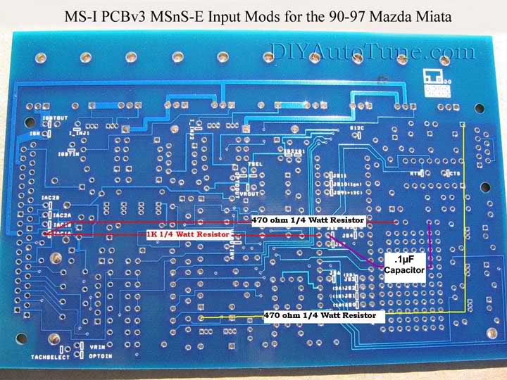
Wire per the directions in the manual, using VR + Pullup for the CKP signal.
From: http://www.msextra.com/doc/ms3/ignition.html#vr
V3.0 board - VR Input + pullup
a) Solder a link between VRIN and TACHSELECT
b) Solder a wire between VrOUT and TSEL
c) Install a 1k resistor (any value 470R - 2k2 is likely ok) in the proto area. Connect one end to the 5V hole and join the other end to VRIN with a jumper wire.
d) With a small screwdriver, turn the pots, R52 and R56, about 12 turns to the fully anticlockwise position (you may feel a "click" when the end position is reached, they can't be damaged by turning too far.) and then turn R56 back about 6 turns clockwise.

Reply
1
1
03-15-2012, 02:45 PM
#8
Elite Member
Thread Starter
iTrader: (24)
Join Date: Jul 2007
Location: Cypress, TX
Posts: 3,759
Total Cats: 35
Going back to the MS1-styled input worked.
Ignore the picture, it was set to rising edge.
What's the reason for the incogruencies between the input methods y'all want me to run? The VR input circuit is the proper circuit, but the opto circuit happens to work, without the adjustment pots?
Ignore the picture, it was set to rising edge.
What's the reason for the incogruencies between the input methods y'all want me to run? The VR input circuit is the proper circuit, but the opto circuit happens to work, without the adjustment pots?
Reply
0
0
03-15-2012, 03:25 PM
#9
Elite Member
Thread Starter
iTrader: (24)
Join Date: Jul 2007
Location: Cypress, TX
Posts: 3,759
Total Cats: 35
Actually, its not quite working yet. When set to falling edge, I'm still not getting complete sync.
When set to rising edge, I get sync, and enough combustion to the point where it will idle on 2 cylinders, though I suppose timing is way off or something bad.
When set to rising edge, I get sync, and enough combustion to the point where it will idle on 2 cylinders, though I suppose timing is way off or something bad.
Reply
0
0

Thread
Thread Starter
Forum
Replies
Last Post
Frank_and_Beans
Supercharger Discussion
13
09-12-2016 08:17 PM
Greasyman
General Miata Chat
2
09-28-2015 10:44 AM


