
Port WI build thread
 01-31-2010, 07:46 PM
#1
Elite Member
Thread Starter
iTrader: (15)

Join Date: Dec 2007
Location: San Antonio, Texas
Posts: 4,847
Total Cats: 27
So there have been some good discussions in several threads here regarding nozzle placement, and single nozzle versus port injection WI. Long story short, I strongly suspect water distribution between the cylinders led to the detonation of my #1 cylinder to the point where I had to pull the motor and replace it.
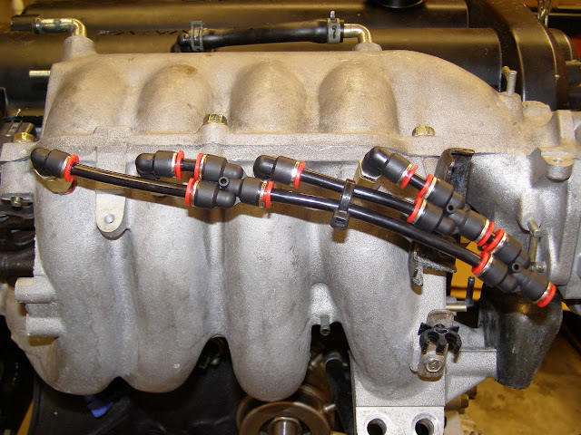
Tired of screwing around with this stuff I decided to spend a little extra money and build a port injection setup. It uses four 2gpm DO external nozzles, and three 2 into 1 DO fittings to split the flow. There are four DO 90 deg elbows on top of each of the nozzles. FWIW I like all of the DO fittings; the elbows swivel even when everything is tight, and the flow splitters are lightweight. They all have the push-lock style tube inserts. I am also adding an Aquamist high speed valve (HSV) that will be PWM controlled by the Adaptronic.
I drilled and tapped a hole in each of the four runners below the upper-to-lower intake manifold flange and mounted the nozzles there. On a related note I completely gutted the upper half of the manifold, and opened up the lower and removed the VICS system. More about that here:
https://www.miataturbo.net/forum/t38809/
Gutted upper:
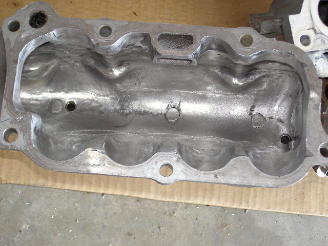
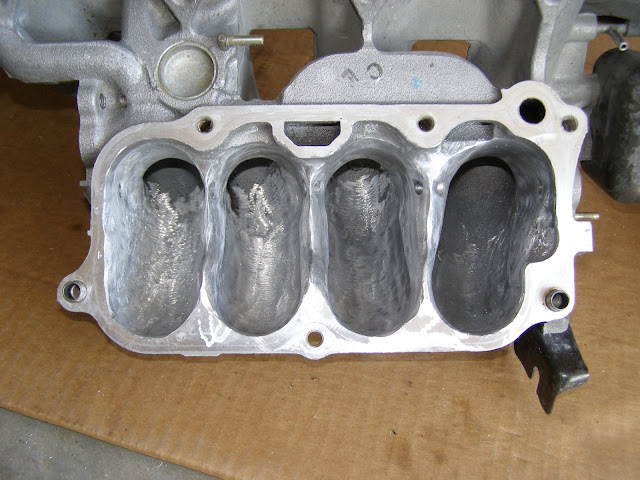
Ported lower, with no VICS
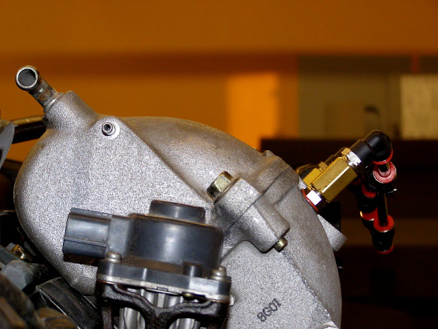
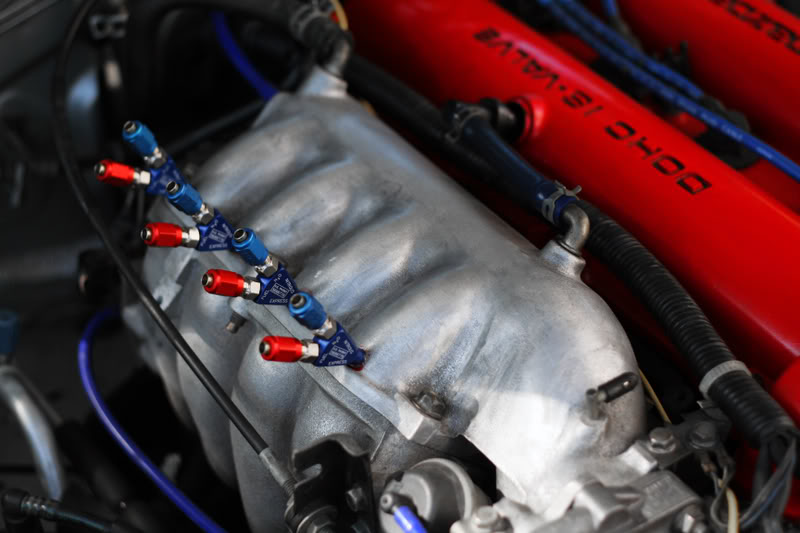
Now for some initial pictures. The engine is out of the car right now and on an engine stand. The first photo shows a shot of the back of the intake manifold. Notice how the nozzles and fittings are below a horizontal plane tangent with the top of the intake manifold. The engine was more or less level when I took the picture. In short, the nozzles won't hit the hood.
This photo shows the location of the four nozzles from below, looking up at the intake manifold.
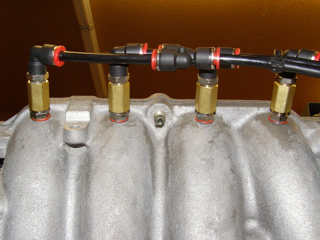
Lastly this shows the tubing 'manifold' that splits the inlet into four flows. From right to left, and in the direction of flow, it is a 1-into-2-into-4 setup. Before someone asks, note that the flow rates (and hence flow velocities) are very, very low, and the difference in the length of the tubing will almost certainly not create enough pressure drop to significantly imbalance the distribution. We are talking about 2gph (or .00056 gallons per second) through each of the approx. 5mm i.d. hoses. With the DO fittings this took all of about 10 minutes to build once the nozzles were installed.
Ideally I would have spot-faced the point where the nozzles go into the manifold so the o-rings would have a better sealing surface. I decided not to do this for a couple of reasons:
- One, the manifold is pretty thin here and I did not want to give up any thickness to a spot face. There are only three or four whole threads in the tapped hole as it is.
- Two, I think it will seal fine anyway, and I put a little gasket sealant on the threads as insurance. If it leaks I'll beef things up by welding tapped bungs on the intake. But if this works, then everyone will know that welding bungs onto the manifold is not required. Not everyone, like I, have access to a nice TIG for aluminum welding (a buddy of mine has one).
More to follow as I get things going.
Tired of screwing around with this stuff I decided to spend a little extra money and build a port injection setup. It uses four 2gpm DO external nozzles, and three 2 into 1 DO fittings to split the flow. There are four DO 90 deg elbows on top of each of the nozzles. FWIW I like all of the DO fittings; the elbows swivel even when everything is tight, and the flow splitters are lightweight. They all have the push-lock style tube inserts. I am also adding an Aquamist high speed valve (HSV) that will be PWM controlled by the Adaptronic.
I drilled and tapped a hole in each of the four runners below the upper-to-lower intake manifold flange and mounted the nozzles there. On a related note I completely gutted the upper half of the manifold, and opened up the lower and removed the VICS system. More about that here:
https://www.miataturbo.net/forum/t38809/
Gutted upper:
Ported lower, with no VICS
Now for some initial pictures. The engine is out of the car right now and on an engine stand. The first photo shows a shot of the back of the intake manifold. Notice how the nozzles and fittings are below a horizontal plane tangent with the top of the intake manifold. The engine was more or less level when I took the picture. In short, the nozzles won't hit the hood.
This photo shows the location of the four nozzles from below, looking up at the intake manifold.
Lastly this shows the tubing 'manifold' that splits the inlet into four flows. From right to left, and in the direction of flow, it is a 1-into-2-into-4 setup. Before someone asks, note that the flow rates (and hence flow velocities) are very, very low, and the difference in the length of the tubing will almost certainly not create enough pressure drop to significantly imbalance the distribution. We are talking about 2gph (or .00056 gallons per second) through each of the approx. 5mm i.d. hoses. With the DO fittings this took all of about 10 minutes to build once the nozzles were installed.
Ideally I would have spot-faced the point where the nozzles go into the manifold so the o-rings would have a better sealing surface. I decided not to do this for a couple of reasons:
- One, the manifold is pretty thin here and I did not want to give up any thickness to a spot face. There are only three or four whole threads in the tapped hole as it is.
- Two, I think it will seal fine anyway, and I put a little gasket sealant on the threads as insurance. If it leaks I'll beef things up by welding tapped bungs on the intake. But if this works, then everyone will know that welding bungs onto the manifold is not required. Not everyone, like I, have access to a nice TIG for aluminum welding (a buddy of mine has one).
More to follow as I get things going.
Last edited by ZX-Tex; 01-31-2010 at 10:16 PM.

Reply
 0
0

0
 02-01-2010, 01:15 AM
#3
Elite Member
iTrader: (1)

Join Date: May 2009
Location: Jacksonville, FL
Posts: 5,155
Total Cats: 406
perfect nozzle placement imo
thats about how my DP nitrous was (before i was turbo of course)
one thought though, have you considered any possibility of uneven distribution due to different length tubing coming from the distribution blocks?
Or do you think that the difference will be insignificant?
thats about how my DP nitrous was (before i was turbo of course)
one thought though, have you considered any possibility of uneven distribution due to different length tubing coming from the distribution blocks?
Or do you think that the difference will be insignificant?
Reply
0
0
02-01-2010, 01:55 AM
#5
Elite Member
Thread Starter
iTrader: (15)
Join Date: Dec 2007
Location: San Antonio, Texas
Posts: 4,847
Total Cats: 27
Unless I am missing something I think the control will be good. I have a few options with the Adaptronic and the HSV. For example, I could scale the PWM DC based on boost. Or I could scale the DC with the fuel injector duty cycle, and have it come on at a set boost threshold. In other words the fuel and water could be held at an approximately fixed ratio. IIRC this is somewhat ideal.
But if you think I am overlooking something though let me know. Input is welcome.
Reply
0
0
02-01-2010, 01:57 AM
#6
Elite Member
Thread Starter
iTrader: (15)
Join Date: Dec 2007
Location: San Antonio, Texas
Posts: 4,847
Total Cats: 27

one thought though, have you considered any possibility of uneven distribution due to different length tubing coming from the distribution blocks?
Or do you think that the difference will be insignificant?
Or do you think that the difference will be insignificant?

Reply
0
0
02-01-2010, 02:22 AM
#7
Elite Member
iTrader: (1)
Join Date: May 2009
Location: Jacksonville, FL
Posts: 5,155
Total Cats: 406
I still have the holes in my manifold from the nitrous and Ive considered going to DP W/I route with them. Im looking forward to seeing how it works out for you.
Reply
0
0
02-01-2010, 02:35 AM
#8
Boost Pope


iTrader: (8)
Join Date: Sep 2005
Location: Chicago. (The less-murder part.)
Posts: 33,020
Total Cats: 6,588
Unless I am missing something I think the control will be good. I have a few options with the Adaptronic and the HSV. For example, I could scale the PWM DC based on boost. Or I could scale the DC with the fuel injector duty cycle, and have it come on at a set boost threshold. In other words the fuel and water could be held at an approximately fixed ratio. IIRC this is somewhat ideal.
The one thing I'd be cautious of is the flow rate through the HSV. It has a fairly narrow orifice. At least, the old one did.
Curiously, it looks like Aquamist has redesigned their whole product line. Not much useful tech into at the website, but I see a new controller, a new "Fast Acting Valve", a switch to ShurFlow style pumps, etc.
More info:
Waterinjection :: View topic - Aquamist HFS-3 system for 2010 ..... "Q and A"
http://www.howertonengineering.com/Aquamist_hfs3.html
http://www.howertonengineering.com/Aquamist_hfs2.html
http://www.aquamist.co.uk/HFS6/HFS-6-3w.pdf
Reply
0
0
02-01-2010, 10:34 AM
#9
Elite Member
Thread Starter
iTrader: (15)
Join Date: Dec 2007
Location: San Antonio, Texas
Posts: 4,847
Total Cats: 27
Scaling WI to fuel PW is pretty much ideal. All the data I've seen shows that for a constant ratio of water to fuel, the anti-knock index is reasonably linear.
The one thing I'd be cautious of is the flow rate through the HSV. It has a fairly narrow orifice. At least, the old one did.
Curiously, it looks like Aquamist has redesigned their whole product line. Not much useful tech into at the website, but I see a new controller, a new "Fast Acting Valve", a switch to ShurFlow style pumps, etc.
Reply
0
0
 02-01-2010, 11:09 AM
#11
Boost Pope
iTrader: (8)
Join Date: Sep 2005
Location: Chicago. (The less-murder part.)
Posts: 33,020
Total Cats: 6,588
One thing that I do wonder about is whether, in a system using an HSV and many nozzles, the relatively great length of tubing between the HSV and the nozzles might act as a dampener. Actually, I can see good and bad here. It'd smooth out pulsations from the valve, but might also decrease the accuracy with which you can control flow. I've noted, for instance, that after I de-power a pump which is connected to a nozzle with maybe 3 or 4 feet of tubing, the nozzle will continue to spray for perhaps a second.
Bench testing of this configuration will be a good thing.
Yeah, scares the ******* out of me, too. One HSV and one flowmeter per nozzle would cover you there. What was that about a single one being expensive?
Reply
0
0
02-01-2010, 05:01 PM
#12
Elite Member
Thread Starter
iTrader: (15)
Join Date: Dec 2007
Location: San Antonio, Texas
Posts: 4,847
Total Cats: 27
One thing that I do wonder about is whether, in a system using an HSV and many nozzles, the relatively great length of tubing between the HSV and the nozzles might act as a dampener. Actually, I can see good and bad here. It'd smooth out pulsations from the valve, but might also decrease the accuracy with which you can control flow. I've noted, for instance, that after I de-power a pump which is connected to a nozzle with maybe 3 or 4 feet of tubing, the nozzle will continue to spray for perhaps a second.
Yeah, scares the ******* out of me, too. One HSV and one flowmeter per nozzle would cover you there. What was that about a single one being expensive?
In other words, there should always be a good supply of mist in the upper intake volume that is available to all of the cylinders. That provides some redundancy in case one valve clogs. Mist will still make it into that runner. This is one advantage of positioning the nozzles where I did, rather than down at the other end of the runners close to the head.
This whole redundancy scheme was my main motivation for gutting the manifold. Improved flow, which is debated elsewhere, was somewhat a secondary consideration.
Reply
0
0
02-01-2010, 05:43 PM
#14
Boost Pope
iTrader: (8)
Join Date: Sep 2005
Location: Chicago. (The less-murder part.)
Posts: 33,020
Total Cats: 6,588
I don't think it's a Shurflo brand, but yeah, they're finally eating crow on that issue. IIRC, they phased in that pump over a year ago on an entry level system. I didn't realize they'd switched over to it completely until yesterday.
Reply
0
0
02-01-2010, 07:31 PM
#16
Elite Member

Join Date: Jul 2005
Posts: 6,420
Total Cats: 84
Exactly.
Are the newer pumps cheaper?
Is the problem of the old one reliability?
I can't believe they switched over to the same cheap pump the ebay kits use, when they could be using one of these:
https://www.miataturbo.net/forum/t20899/
The Shurflo pumps are optimized for the wrong thing. They are high volume high pressure pumps; a WI pump can be a lot smaller because they are LOW volume high pressure. The frakkin pump needs to be no bigger than a *&^ fuel pump.
Sheesh.
Reply
0
0
02-01-2010, 07:55 PM
#17

Exactly.
Are the newer pumps cheaper?
Is the problem of the old one reliability?
I can't believe they switched over to the same cheap pump the ebay kits use, when they could be using one of these:
https://www.miataturbo.net/forum/t20899/
The Shurflo pumps are optimized for the wrong thing. They are high volume high pressure pumps; a WI pump can be a lot smaller because they are LOW volume high pressure. The frakkin pump needs to be no bigger than a *&^ fuel pump.
Sheesh.
Are the newer pumps cheaper?
Is the problem of the old one reliability?
I can't believe they switched over to the same cheap pump the ebay kits use, when they could be using one of these:
https://www.miataturbo.net/forum/t20899/
The Shurflo pumps are optimized for the wrong thing. They are high volume high pressure pumps; a WI pump can be a lot smaller because they are LOW volume high pressure. The frakkin pump needs to be no bigger than a *&^ fuel pump.
Sheesh.
Reply
0
0
02-01-2010, 08:06 PM
#18
Elite Member
Join Date: Jul 2005
Posts: 6,420
Total Cats: 84
auqaflo pump? Is that a Shurflo pump?
My beef with the Shurflo is its sheer SIZE.
Why couldn't they have developed something better that is only a bit pricier than the Shurflo? They went thru the trouble of designing their older pump...
My beef with the Shurflo is its sheer SIZE.
Why couldn't they have developed something better that is only a bit pricier than the Shurflo? They went thru the trouble of designing their older pump...
Reply
0
0
02-01-2010, 08:08 PM
#19
Sorry, meant Aquatec. AQUATEC WATER SYSTEMS INC. Precision Diaphragm Pumps, Flow Control Components, Water Pumps, Engineering Expertise I agree they are big, but from a design and engineering perspective its a simple choice. It works, its proven, its effective. Sure you might not like the size, but 99.9% of customers don't care. Why spend 2x as much to import or custom make a pump?
Reply
0
0


