
Aerodynamic Discussion Thread
 12-26-2013, 12:30 AM
#461

After reading a motorcycle article test on "Ram Air" I concluded the benefits were virtually nonexistent for a NA power track car at the speeds I normally see. When I plugged the same "Ram Air" pressure data into a compressor MAP however the result was worth the effort. If I recall it was worth an extra 1 PSI at speed on my supercharged application. On a turbo application you may not see a boost increase just lower IAT's. It will depend on they way you control the waste gate.
The magic is a result of the way FI multiplies available air. The slight pressure increase on the intake side will be doubled on the output side if you are running 1 bar of boost. (SC application)
I plan to feed high pressure air from the bumper to the intake. I will be able to log the pressure difference at speed with the MAP sensor to prove the merits of the idea.

Reply
 0
0

0
12-26-2013, 12:47 PM
#462
Supporting Vendor

iTrader: (3)

Join Date: Jul 2006
Location: San Diego
Posts: 3,303
Total Cats: 1,216
A very interesting note. I had not heard of any testing for boosted applications before. That it magnifies the pressure increase is pretty cool. This is probably more handy for a supercharged setup where more boost is not so easy to come by, whereas with a turbo with a boost controller, the same net effect is easy to replicate, though the cooler air is still a benefit.
-Ryan
-Ryan

Reply
0
0
12-26-2013, 05:30 PM
#463
It will be interesting to see the results on my car. I have to believe the motorcycle pressure is going to be less than that of a Miata bumper. Unlike a motorcycle which has a slippery profile the Miata bumper has lots more surface area to build up pressure. This will only compound the "ram air" effects.
Reply
0
0
12-26-2013, 05:59 PM
#464

It will be interesting to see the results on my car. I have to believe the motorcycle pressure is going to be less than that of a Miata bumper. Unlike a motorcycle which has a slippery profile the Miata bumper has lots more surface area to build up pressure. This will only compound the "ram air" effects.
I bought a pressurized airbox for my RC51 that worked by removing the stock plastic airbox and essentially making a lower clamshell that fit over the engine. The top of the clamshell was the gas tank. The air box volume quadrupled. It worked really well, but the intake noise was much more pronounced...not that I minded.


Reply
0
0
12-26-2013, 06:59 PM
#465

It will be interesting to see the results on my car. I have to believe the motorcycle pressure is going to be less than that of a Miata bumper. Unlike a motorcycle which has a slippery profile the Miata bumper has lots more surface area to build up pressure. This will only compound the "ram air" effects.
Reply
0
0
12-31-2013, 08:55 PM
#466
Senior Member

Join Date: Dec 2012
Location: Charlotte, NC
Posts: 538
Total Cats: 64
On the Ram Air note, I will add that coming from a drag racing background, specifically carbureted, we would see significant gains using cowl induction or forward facing hood scoops. Typically, the gains were attributed on N/A and nitrous motors from a reduction in IAT, or a stronger venturi signal. Without the ducted air setups or adequate underhood clearance, turbulence would lead to signal/fuel distribution problems in carb'd applications.
I'm about at the point where I may see how short an air filter I can go with, and if need be, just plop one of these on the hood with an open element.
I'm about at the point where I may see how short an air filter I can go with, and if need be, just plop one of these on the hood with an open element.
Reply
0
0
02-05-2014, 11:21 PM
#467
Junior Member

Join Date: Jun 2013
Location: Raleigh, NC
Posts: 122
Total Cats: -10
I put this up because of the new active diffusers (front and rear) and that is so cool
La Ferrari - YouTube
La Ferrari - YouTube
Reply
0
0
02-06-2014, 12:32 AM
#468

I agree with this. I was doing some dyno tuning last year and my IATs kept creeping higher and higher. My intake is 3 pieces of silicon hose clamped together (2 90 degree elbows, then a long section that points back toward the firewall) so I loosened a hose clamp and rotated the intake to point straight up. I think IATs dropped by 60 or 80 degrees, down to ambient. I picked up 2 or 3 peak hp, but midrange gains were huge- I think 8lb*ft at one point. I've had a NACA duct pointing straight at the air filter ever since. Minimal drag increase but constant supply of ambient temp air for the filter.
Reply
0
0
02-06-2014, 01:02 PM
#469
Senior Member
iTrader: (1)

Join Date: Dec 2008
Location: Manassas, Virginia
Posts: 1,242
Total Cats: 57
ooooh I like that active diffuser design. Great idea changing the angle of attack based on the spoiler's. I wonder how much that shifts the balance of the car rearword on braking. More than just the active spoiler "airbrake" alone. Could be done fairly easily with connecting rods between the two...
I'm really excited to be seeing more and more active aero in production cars. I was worried we'd never really see that since active aero R&D is of no use to factory race teams since (I think) there are no racing series that allow it.
So basically the flaps in the under tray of LaFerrari are used to control air pressure under the car to compliment air pressure over the car? I saw that when the rear spoiler was raised, so was the rear diffuser flap (and vice versa). Are these two things connected in a way where increasing the diffuser AOA helps the spoiler create more downforce at higher AOAs? The only other explanation I could think of is that they are independant of each other and that each element moves to create either less drag or more downforce depending on the circumstances. The only thing that confuses me with that theory is that I was under the impression that a diffuser gives downforce with (relatively) no additional drag. So why is it adjustable?
Reply
0
0
 02-07-2014, 02:01 AM
#471
Senior Member
iTrader: (1)
Join Date: Dec 2008
Location: Manassas, Virginia
Posts: 1,242
Total Cats: 57
So as the AOA of the spoiler increases, pressure behind the car decreases (accidentally wrote increases) which lets the diffuser run a higher AOA without getting separation of the laminar flow?
Also, how are the font flaps designed to change with conditions? It looked to me like they are really just there to relieve pressure built up by the splitter into the under tray. This would give less downforce up front and possibly add more to the rear by flowing more air through the diffuser. Maybe it just makes the car more slippery on the straights. Thoughts?
Also, how are the font flaps designed to change with conditions? It looked to me like they are really just there to relieve pressure built up by the splitter into the under tray. This would give less downforce up front and possibly add more to the rear by flowing more air through the diffuser. Maybe it just makes the car more slippery on the straights. Thoughts?
Last edited by mx5autoxer; 02-07-2014 at 12:01 PM.
Reply
0
0
02-07-2014, 08:23 AM
#472
Junior Member
Join Date: Jun 2013
Location: Raleigh, NC
Posts: 122
Total Cats: -10
So as the AOA of the spoiler increases, pressure behind the car increases which lets the diffuser run a higher AOA without getting separation of the laminar flow?
Also, how are the font flaps designed to change with conditions? It looked to me like they are really just there to relieve pressure built up by the splitter into the under tray. This would give less downforce up front and possibly add more to the rear by flowing more air through the diffuser. Maybe it just makes the car more slippery on the straights. Thoughts?
Also, how are the font flaps designed to change with conditions? It looked to me like they are really just there to relieve pressure built up by the splitter into the under tray. This would give less downforce up front and possibly add more to the rear by flowing more air through the diffuser. Maybe it just makes the car more slippery on the straights. Thoughts?
Since I'm planning to do an air brake down the road, an adjustable diffuser would be fun to add if I can do the math right to make sure it actually works...

P.S. for the front flaps, based on the quick view we get as the video slides past it looks like there is an opening above the flap and a channel after so my guess is that when the diffuser and spoiler incease their respective angles they require more air to be effective so the flaps in front drop added air under the car. Things you can do when you have ferrari's budget, engineers, CFD, and windtunnels o.O
Last edited by ecc3189; 02-07-2014 at 08:29 AM. Reason: answered second question
Reply
0
0
02-07-2014, 09:08 AM
#473
Junior Member
Join Date: Jun 2013
Location: Raleigh, NC
Posts: 122
Total Cats: -10
On the Ram Air note, I will add that coming from a drag racing background, specifically carbureted, we would see significant gains using cowl induction or forward facing hood scoops. Typically, the gains were attributed on N/A and nitrous motors from a reduction in IAT, or a stronger venturi signal. Without the ducted air setups or adequate underhood clearance, turbulence would lead to signal/fuel distribution problems in carb'd applications.
I'm about at the point where I may see how short an air filter I can go with, and if need be, just plop one of these on the hood with an open element.
I'm about at the point where I may see how short an air filter I can go with, and if need be, just plop one of these on the hood with an open element.
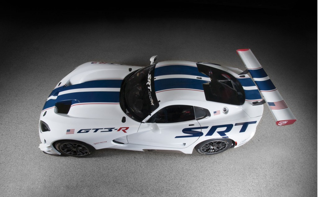
Why not try a design like the ford GT or viper with a bifurcated radiator duct and have an intake box and filter on the nose and the radiator duct split around the intake tube going into the throttle body:

Last edited by ecc3189; 02-07-2014 at 09:09 AM. Reason: readibility
Reply
0
0
02-07-2014, 12:14 PM
#474
Senior Member
iTrader: (1)
Join Date: Dec 2008
Location: Manassas, Virginia
Posts: 1,242
Total Cats: 57
P.S. for the front flaps, based on the quick view we get as the video slides past it looks like there is an opening above the flap and a channel after so my guess is that when the diffuser and spoiler incease their respective angles they require more air to be effective so the flaps in front drop added air under the car. Things you can do when you have ferrari's budget, engineers, CFD, and windtunnels o.O
Reply
0
0
02-07-2014, 09:37 PM
#475
Senior Member
Join Date: Dec 2012
Location: Charlotte, NC
Posts: 538
Total Cats: 64
Supe, you have a center, forward facing intake and you want to make sure you get cool air while also ducting the radiator to the hood right?
Why not try a design like the ford GT or viper with a bifurcated radiator duct and have an intake box and filter on the nose and the radiator duct split around the intake tube going into the throttle body:
Why not try a design like the ford GT or viper with a bifurcated radiator duct and have an intake box and filter on the nose and the radiator duct split around the intake tube going into the throttle body:
Thankfully, I think I have enough clearance having dropped the brake booster and gone to dual masters inside the car to make an offset cowl induction setup that should work without sucking in hot air.
Reply
0
0
04-07-2014, 01:58 PM
#476
Supporting Vendor
iTrader: (3)
Join Date: Jul 2006
Location: San Diego
Posts: 3,303
Total Cats: 1,216
Searching for quite a while on the internetz and not finding a straight answer..
We know there's a magic ratio of about 1:3 for duct opening size to heat exchanger surface area, but that's for a straightforward single duct for a single exchanger.
Now, if you're supplying multiple heat exchangers with a given duct (such as with a radiator and intercooler like most of us have) then do you add the surface areas of both together, which would then require a bumper opening in some cases almost double the size of the opening for a radiator-only duct?
If the heat exchangers are stacked together, perhaps there is some average between the two that is ideal, but especially for a setup which has gone through the trouble to seperate the surface of the radiator from the surface of the intercooler so they both get their own air, it seems to me that the duct opening needs to grow much larger than the roughly 96 square inches opening size that we usually see agreed upon for miatas (1/3 of 12"x24" radiator surface)
-Ryan
Reply
0
0
04-07-2014, 02:06 PM
#477

If the heat exchangers are are stacked like in a normal setup I would, duct the back of the intercooler directly to the radiator, which means some section of the radiator the same size as the intercooler core is going to get hotter air than the rest of it. But if you didnt do that flow through the intercooler would be non-existent since the pressure on both sides of the core would be more or less equal. Unless you can make the intercooler exit not directly into the radiator, like under it or something. So then the main duct to the radiator only needs to be the size of the radiator - the intercooler blocking the flow /3.
Every time I think about ducting I think about just running an EP style nose because it would make connecting the ducting to the bumper about a billion times easier.
Every time I think about ducting I think about just running an EP style nose because it would make connecting the ducting to the bumper about a billion times easier.
Reply
0
0
 04-07-2014, 02:26 PM
#479
Junior Member
Join Date: Jun 2013
Location: Raleigh, NC
Posts: 122
Total Cats: -10
I think Leafy has it right, you wouldn't add the two areas. You would have to run calculations on the heat gain of the air going through the IC and the area of the radiator that it affects. Then do some funny math where you took the free area of the radiator with ambient air plus the area covered by the intercooler with the heated air and figure out what the new total inlet area you would need.
Or just seal the ducting from the bumper inlet to the radiator and the air will flow through both. KISS as they would say
Or just seal the ducting from the bumper inlet to the radiator and the air will flow through both. KISS as they would say
Reply
0
0


